SFI SYSTEM > MIL Circuit |

for Preparation Click here
DESCRIPTION
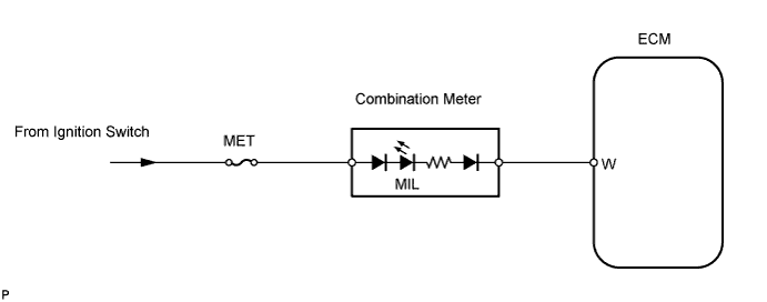
The MIL is used to inform the user when the ECM has detected a vehicle malfunction.By turning the ignition switch ON, power is supplied to the MIL circuit, and the ECM provides the circuit ground that illuminates the MIL.
Operation of the MIL should be checked visually:
When the ignition switch is first turned ON, the MIL should illuminate. When the engine is started, the MIL should turn off.
WIRING DIAGRAM
INSPECTION PROCEDURE
| 1.CHECK THAT MIL IS ILLUMINATED |
Perform troubleshooting in accordance with the chart below.
- Result:
Condition Proceed to MIL remains ON A MIL does not illuminate B
|
| ||||
| A | |
| 2.CHECK IF MIL TURNS OFF |
Connect the intelligent tester to the DLC3.
Turn the ignition switch ON and turn the intelligent tester ON.
Check if DTCs have been stored (Click here). If DTCs are present, write them down.
Clear the DTCs using the intelligent tester (Click here).
Check that the MIL turns off.
- OK:
- The MIL turns off.
|
| ||||
| NG | |
| 3.CHECK WIRE HARNESS (FOR SHORT) |
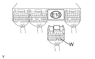 |
Disconnect the E10 ECM connector.
Turn the ignition switch ON.
Check that the MIL is not illuminated.
- OK:
- The MIL is not illuminated.
|
| ||||
| NG | |
| 4.CHECK WIRE HARNESS (ECM - COMBINATION METER) |
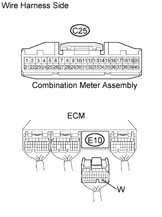 |
Disconnect the E10 ECM connector.
Disconnect the C25 combination meter connector.
Measure the resistance of the wire harness side connectors.
- Standard resistance:
Tester Connection Specified Condition E10-30 (W) - C25-39 Below 1 Ω E10-30 (W) or C25-39 - Body ground 10 kΩ or higher
|
| ||||
| OK | ||
| ||
| 5.CHECK IF MIL ILLUMINATES |
Check that the MIL illuminates when turning the ignition switch ON.
- OK:
- The MIL illuminates.
|
| ||||
| NG | |
| 6.CHECK THAT ENGINE STARTS |
Turn the ignition switch ON.
Start the engine.
| Result | Proceed To |
| Engine starts | A |
| Engine does not start* | B |
- HINT:
- *: The intelligent tester cannot communicate with the ECM.
|
| ||||
| A | |
| 7.INSPECT COMBINATION METER ASSEMBLY (MIL CIRCUIT) |
See the combination meter troubleshooting procedure (Click here).
|
| ||||
| OK | ||
| ||