CAN COMMUNICATION SYSTEM > TERMINALS OF ECU |

for Preparation Click here
- NOTICE:
- Turn the ignition switch off before measuring the resistance of the CAN bus main wires and CAN bus branch wires.
- After the ignition switch is turned off, check that the key reminder warning system and light reminder warning system are not in operation.
- Before measuring the resistance, leave the vehicle as is for at least 1 minute and do not operate the ignition switch, any other switches or the doors. If any doors need to be opened in order to check the connectors, open the doors and leave them open.
- HINT:
- Operating the ignition switch, any other switches or a door triggers related ECU and sensor communication on the CAN.
- This communication will cause the resistance value to change.
- NOTICE:
- This section describes the standard CAN values for all CAN related components.
| JUNCTION CONNECTOR FOR CAN NO. 1 BUS |
CAN No. 1 junction connector (TMC made)

Text in Illustration *a Front view of wire harness connector
(to CAN No. 1 Junction Connector)- - No. 1 Junction Connector Wiring Color Connect to E58-2 (CANH) G Combination meter E58-13 (CANL) W Combination meter E58-3 (CANH) SB Power steering ECU E58-14 (CANL) W Power steering ECU E58-4 (CANH) V Air conditioning amplifier E58-15 (CANL) W Air conditioning amplifier E58-5 (CANH) BR Steering angle sensor E58-16 (CANL) W Steering angle sensor E58-6 (CANH) L Yaw rate sensor E58-17 (CANL) W Yaw rate sensor E58-7 (CANH) LG DLC3 E58-18 (CANL) W DLC3 E58-8 (CANH) R Main body ECU E58-19 (CANL) W Main body ECU E58-9 (CANH) Y Center airbag sensor assembly E58-20 (CANL) W Center airbag sensor assembly E58-10 (CANH) B CAN No. 2 junction connector E58-21 (CANL) W CAN No. 2 junction connector E58-11 (CANH) GR Accessory gateway E58-22 (CANL) W Accessory gateway CAN No. 1 junction connector (Except TMC made)
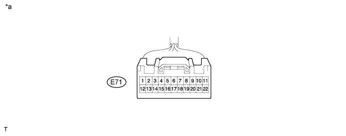
Text in Illustration *a Front view of wire harness connector
(to CAN No. 1 Junction Connector)- - No. 1 Junction Connector Wiring Color Connect to E71-1 (CANH) R Main body ECU E71-12 (CANL) W Main body ECU E71-2 (CANH) LG DLC3 E71-13 (CANL) W DLC3 E71-3 (CANH) SB Power steering ECU E71-14 (CANL) W Power steering ECU E71-4 (CANH) G Combination meter E71-15 (CANL) W Combination meter E71-5 (CANH) Y Center airbag sensor assembly E71-16 (CANL) W Center airbag sensor assembly E71-6 (CANH) B CAN No. 2 junction connector E71-17 (CANL) W CAN No. 2 junction connector E71-7 (CANH) V Air conditioning amplifier E71-18 (CANL) W Air conditioning amplifier E71-8 (CANH) BR Steering angle sensor E71-19 (CANL) W Steering angle sensor E71-9 (CANH) L Yaw rate sensor E71-20 (CANL) W Yaw rate sensor E71-11 (CANH) GR Accessory gateway E71-22 (CANL) W Accessory gateway CAN No. 2 junction connector
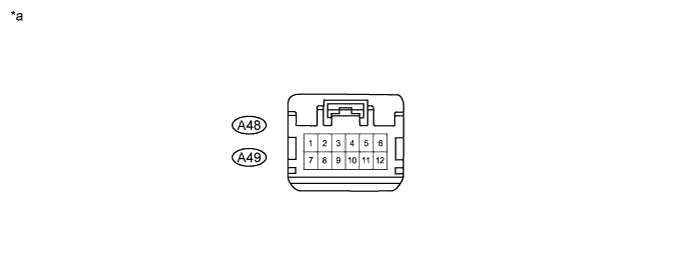
Text in Illustration *a Front view of wire harness connector
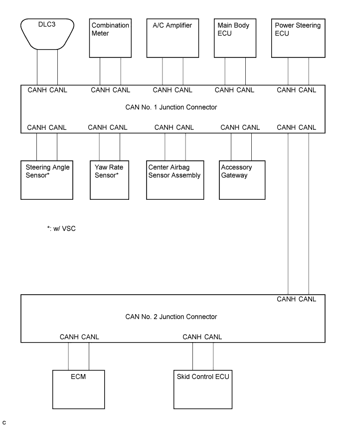
(to CAN No. 2 Junction Connector)- - No. 2 Junction Connector Wiring Color Connect to A48-1 (CANH) R Skid control ECU A48-3 (CANL) W Skid control ECU A48-2 (CANH) Y ECM A48-4 (CANL) W ECM A49-6 (CANH) B CAN No. 1 junction connector A49-4 (CANL) W CAN No. 1 junction connector The connection diagram of the components which are connected to the CAN junction connector
| JUNCTION CONNECTOR FOR CAN MS BUS |
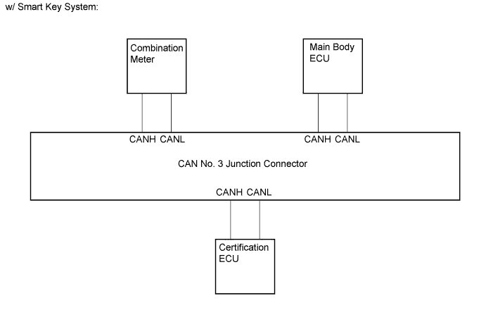
CAN No. 3 junction connector
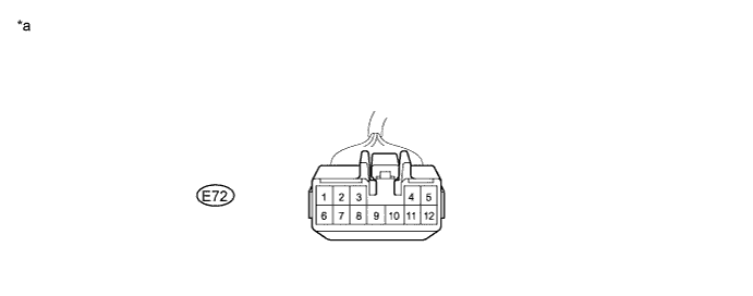
Text in Illustration *a Front view of wire harness connector
(to CAN No. 3 Junction Connector)- - No. 3 Junction Connector Wiring Color Connect to E72-1 (CANH) SB Certification ECU E72-6 (CANL) W Certification ECU E72-2 (CANH) G Combination meter E72-7 (CANL) W Combination meter E72-3 (CANH) R Main body ECU E72-8 (CANL) W Main body ECU The connection diagram of the components which are connected to the CAN junction connector.
| DLC3 |
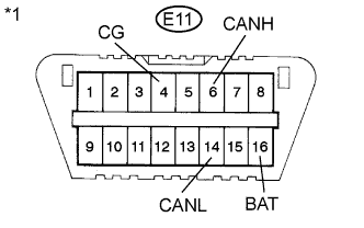
Measure the resistance according to the value(s) in the table below.
Text in Illustration *1 DLC3 - Standard Resistance:
Terminal No. (Symbol) Wiring Color Condition Specified Condition E11-6 (CANH) - E11-14 (CANL) LG - W Ignition switch off 54 to 69 Ω E11-6 (CANH) - E11-4 (CG) LG - W-B Ignition switch off 200 Ω or higher E11-14 (CANL) - E11-4 (CG) W - W-B Ignition switch off 200 Ω or higher E11-6 (CANH) - E11-16 (BAT) LG - G*1
LG - LG*2Cable is disconnected from negative (-) battery terminal 6 kΩ or higher E11-14 (CANL) - E11-16 (BAT) W - G*1
W - LG*2Cable is disconnected from negative (-) battery terminal 6 kΩ or higher
- *1: TMC made
- *2: except TMC made
 |
| SKID CONTROL ECU WITH ACTUATOR (w/ VSC) |
Disconnect the connector from the skid control ECU.
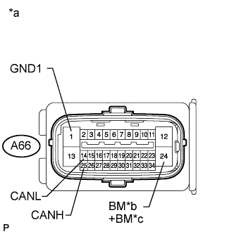
Text in Illustration *a Front view of wire harness connector
(to Skid Control ECU with Actuator)*b TMC Made *c Except TMC Made Measure the resistance according to the value(s) in the table below.
- Standard Resistance:
Terminal No. (Symbol) Wiring Color Condition Specified Condition A66-25 (CANH) - A66-14 (CANL) R - W Ignition switch off 54 to 69 Ω A66-25 (CANH) - A66-1 (GND1) R - W-B Ignition switch off 200 Ω or higher A66-14 (CANL) - A66-1 (GND1) W - W-B Ignition switch off 200 Ω or higher A66-25 (CANH) - A66-24 (BM)*1
A66-25 (CANH) - A66-24 (+BM)*2R - L Cable is disconnected from negative (-) battery terminal 6 kΩ or higher A66-14 (CANL) - A66-24 (BM)*1
A66-14 (CANL) - A66-24 (+BM)*2W - L Cable is disconnected from negative (-) battery terminal 6 kΩ or higher
- *1: TMC made
- *2: except TMC made
 |
| SKID CONTROL ECU WITH ACTUATOR (w/o VSC) |
Disconnect the connector from the skid control ECU.
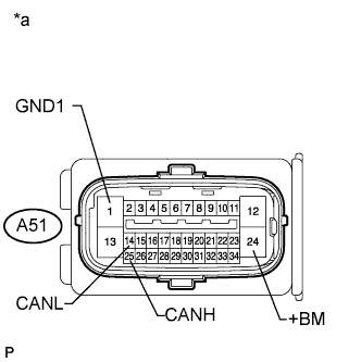
Text in Illustration *a Front view of wire harness connector
(to Skid Control ECU with Actuator)Measure the resistance according to the value(s) in the table below.
- Standard Resistance:
Terminal No. (Symbol) Wiring Color Condition Specified Condition A51-25 (CANH) - A51-14 (CANL) R - W Ignition switch off 54 to 69 Ω A51-25 (CANH) - A51-1 (GND1) R - W-B Ignition switch off 200 Ω or higher A51-14 (CANL) - A51-1 (GND1) W - W-B Ignition switch off 200 Ω or higher A51-25 (CANH) - A51-24 (+BM) R - L Cable is disconnected from negative (-) battery terminal 6 kΩ or higher A51-14 (CANL) - A51-24 (+BM) W - L Cable is disconnected from negative (-) battery terminal 6 kΩ or higher
 |
| STEERING ANGLE SENSOR |
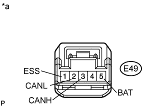
Disconnect the connector from the steering angle sensor.
Text in Illustration *a Front view of wire harness connector
(to Steering Angle Sensor)Measure the resistance according to the value(s) in the table below.
- Standard Resistance:
Terminal No. (Symbol) Wiring Color Condition Specified Condition E49-3 (CANH) - E49-2 (CANL) BR - W Ignition switch off 54 to 69 Ω E49-3 (CANH) - E49-1 (ESS) BR - W-B Ignition switch off 200 Ω or higher E49-2 (CANL) - E49-1 (ESS) W - W-B Ignition switch off 200 Ω or higher E49-3 (CANH) - E49-5 (BAT) BR - W*1
BR - R*2Cable is disconnected from negative (-) battery terminal 6 kΩ or higher E49-2 (CANL) - E49-5 (BAT) W - W*1
W - R*2Cable is disconnected from negative (-) battery terminal 6 kΩ or higher
- *1: TMC made
- *2: except TMC made
 |
| YAW RATE SENSOR |
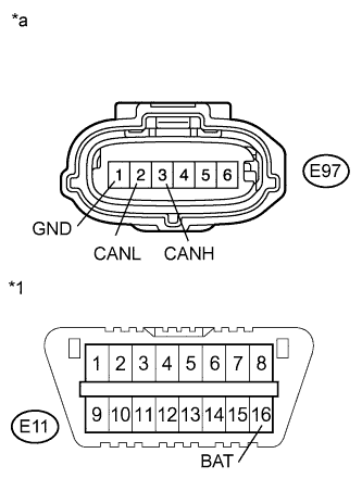
Disconnect the connector from the yaw rate sensor.
Text in Illustration *1 DLC3 *a Front view of wire harness connector
(to Yaw Rate Sensor)Measure the resistance according to the value(s) in the table below.
- Standard Resistance:
Terminal No. (Symbol) Wiring Color Condition Specified Condition E97-3 (CANH) - E97-2 (CANL) L - W Ignition switch off 54 to 69 Ω E97-3 (CANH) - E97-1 (GND) L - W-B Ignition switch off 200 Ω or higher E97-2 (CANL) - E97-1 (GND) W - W-B Ignition switch off 200 Ω or higher E97-3 (CANH) - E11-16 (BAT) L - G*1
L - LG*2Cable is disconnected from negative (-) battery terminal 6 kΩ or higher E97-2 (CANL) - E11-16 (BAT) W - G*1
W - LG*2Cable is disconnected from negative (-) battery terminal 6 kΩ or higher
- *1: TMC made
- *2: except TMC made
 |
| CENTER AIRBAG SENSOR |
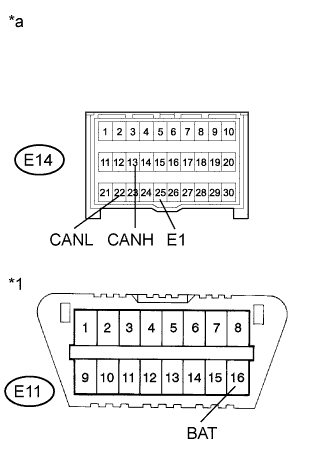
Disconnect the connector from the center airbag sensor.
Text in Illustration *1 DLC3 *a Front view of wire harness connector
(to Center Airbag Sensor)Measure the resistance according to the value(s) in the table below.
- Standard Resistance:
Terminal No. (Symbol) Wiring Color Condition Specified Condition E14-13 (CANH) - E14-22 (CANL) Y - W Ignition switch off 54 to 69 Ω E14-13 (CANH) - E14-25 (E1) Y - W-B Ignition switch off 200 Ω or higher E14-22 (CANL) - E14-25 (E1) W - W-B Ignition switch off 200 Ω or higher E14-13 (CANH) - E11-16 (BAT) Y - G*1
Y - LG*2Cable is disconnected from negative (-) battery terminal 6 kΩ or higher E14-22 (CANL) - E11-16 (BAT) W - G*1
W - LG*2Cable is disconnected from negative (-) battery terminal 6 kΩ or higher
- *1: TMC made
- *2: except TMC made
 |
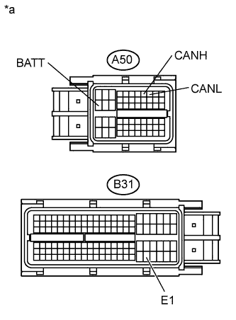
| ECM (for 2AZ-FE) |
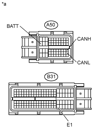
Disconnect the connector from the ECM.
Text in Illustration *a Front view of wire harness connector
(to ECM)Measure the resistance according to the value(s) in the table below.
- Standard Resistance:
Terminal No. (Symbol) Wiring Color Condition Specified Condition A50-41 (CANH) - A50-49 (CANL) Y - W Ignition switch off 108 to 132 Ω A50-41 (CANH) - B31-104 (E1) Y - BR Ignition switch off 200 Ω or higher A50-49 (CANL) - B31-104 (E1) W - BR Ignition switch off 200 Ω or higher A50-41 (CANH) - A50-20 (BATT) Y - P Cable is disconnected from negative (-) battery terminal 6 kΩ or higher A50-49 (CANL) - A50-20 (BATT) W - P Cable is disconnected from negative (-) battery terminal 6 kΩ or higher
 |
| ECM (for 2ZR-FE) |
Disconnect the connector from the ECM.
Text in Illustration *a Front view of wire harness connector
(to ECM)Measure the resistance according to the value(s) in the table below.
- Standard Resistance:
Terminal No. (Symbol) Wiring Color Condition Specified Condition A50-8 (CANH) - A50-9 (CANL) Y - W Ignition switch off 108 to 132 Ω A50-8 (CANH) - B31-105 (E1) Y - BR Ignition switch off 200 Ω or higher A50-9 (CANL) - B31-105 (E1) W - BR Ignition switch off 200 Ω or higher A50-8 (CANH) - A50-20 (BATT) Y - P Cable is disconnected from negative (-) battery terminal 6 kΩ or higher A50-9 (CANL) - A50-20 (BATT) W - P Cable is disconnected from negative (-) battery terminal 6 kΩ or higher
 |
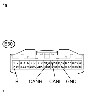
| AIR CONDITIONING AMPLIFIER (for Automatic Air Conditioning System) |
Disconnect the air conditioning amplifier connector.
Text in Illustration *a Front view of wire harness connector
(to Air Conditioning Amplifier)Measure the resistance according to the value(s) in the table below.
- Standard Resistance:
Terminal No. (Symbol) Wiring Color Condition Specified Condition E30-11 (CANH) - E30-12 (CANL) V - W Ignition switch off 54 to 69 Ω E30-11 (CANH) - E30-14 (GND) V - W-B Ignition switch off 200 Ω or higher E30-12 (CANL) - E30-14 (GND) W - W-B Ignition switch off 200 Ω or higher E30-11 (CANH) - E30-21 (B) V - W*1
V - BR*2Cable is disconnected from negative (-) battery terminal 6 kΩ or higher E30-12 (CANL) - E30-21 (B) W - W*1
W - BR*2Cable is disconnected from negative (-) battery terminal 6 kΩ or higher
- *1: TMC made
- *2: except TMC made
 |
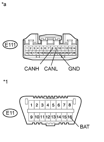
| AIR CONDITIONING AMPLIFIER (for Manual Air Conditioning System, 2ZR-FE) |
Disconnect the air conditioning amplifier connector.
Text in Illustration *1 DLC3 *a Front view of wire harness connector
(to Air Conditioning Amplifier)Measure the resistance according to the value(s) in the table below.
- Standard Resistance:
Terminal No. (Symbol) Wiring Color Condition Specified Condition E111-8 (CANH) - E111-9 (CANL) V - W Ignition switch off 54 to 69 Ω E111-8 (CANH) - E111-24 (GND) V - W-B Ignition switch off 200 Ω or higher E111-9 (CANL) - E111-24 (GND) W - W-B Ignition switch off 200 Ω or higher E111-8 (CANH) - E11-16 (BAT) V - G*1
V - LG*2Cable is disconnected from negative (-) battery terminal 6 kΩ or higher E111-9 (CANL) - E11-16 (BAT) W - G*1
W - LG*2Cable is disconnected from negative (-) battery terminal 6 kΩ or higher
- *1: TMC made
- *2: except TMC made
 |
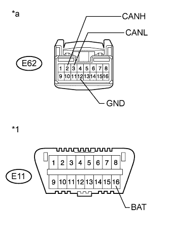
| AIR CONDITIONING AMPLIFIER (for Manual Air Conditioning System, 2AZ-FE) |
Disconnect the air conditioning amplifier connector.
Text in Illustration *1 DLC3 *a Front view of wire harness connector
(to Air Conditioning Amplifier)Measure the resistance according to the value(s) in the table below.
- Standard Resistance:
Terminal No. (Symbol) Wiring Color Condition Specified Condition E62-2 (CANH) - E62-3 (CANL) V - W Ignition switch off 54 to 69 Ω E62-2 (CANH) - E62-12 (GND) V - W-B Ignition switch off 200 Ω or higher E62-3 (CANL) - E62-12 (GND) W - W-B Ignition switch off 200 Ω or higher E62-2 (CANH) - E11-16 (BAT) V - LG Cable is disconnected from negative (-) battery terminal 6 kΩ or higher E62-3 (CANL) - E11-16 (BAT) W - LG Cable is disconnected from negative (-) battery terminal 6 kΩ or higher
 |
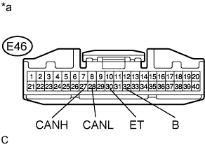
| COMBINATION METER (TMC made) |
Disconnect the connector from the combination meter.
Text in Illustration *a Front view of wire harness connector
(to Combination Meter)Measure the resistance according to the value(s) in the table below.
- Standard Resistance:
Terminal No. (Symbol) Wiring Color Condition Specified Condition E46-27 (CANH) - E46-28 (CANL) G - W Ignition switch off 108 to 132 Ω E46-27 (CANH) - E46-30 (ET) G - BR Ignition switch off 200 Ω or higher E46-28 (CANL) - E46-30 (ET) W - BR Ignition switch off 200 Ω or higher E46-27 (CANH) - E46-32 (B) G - W Cable is disconnected from negative (-) battery terminal 6 kΩ or higher E46-28 (CANL) - E46-32 (B) W - W Cable is disconnected from negative (-) battery terminal 6 kΩ or higher
 |
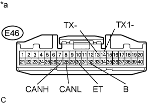
| COMBINATION METER (except TMC made) |
Disconnect the connector from the combination meter.
Text in Illustration *a Front view of wire harness connector
(to Combination Meter)Measure the resistance according to the value(s) in the table below.
- Standard Resistance:
Terminal No. (Symbol) Wiring Color Condition Specified Condition E46-27 (CANH) - E46-28 (CANL) G - W Ignition switch off 108 to 132 Ω E46-27 (CANH) - E46-30 (ET) G - W-B Ignition switch off 200 Ω or higher E46-28 (CANL) - E46-30 (ET) W - W-B Ignition switch off 200 Ω or higher E46-27 (CANH) - E46-32 (B) G - R Cable is disconnected from negative (-) battery terminal 6 kΩ or higher E46-28 (CANL) - E46-32 (B) W - R Cable is disconnected from negative (-) battery terminal 6 kΩ or higher E46-14 (TX1-) - E46-13 (TX-)*1 G - W Ignition switch off 108 to 132 Ω E46-14 (TX1-) - E46-30 (ET)*1 G - W-B Ignition switch off 200 Ω or higher E46-13 (TX-) - E46-30 (ET)*1 W - W-B Ignition switch off 200 Ω or higher E46-14 (TX1-) - E46-32 (B)*1 G - R Cable is disconnected from negative (-) battery terminal 6 kΩ or higher E46-13 (TX-) - E46-32 (B)*1 W - R Cable is disconnected from negative (-) battery terminal 6 kΩ or higher
- *1: w/ Smart key system
 |
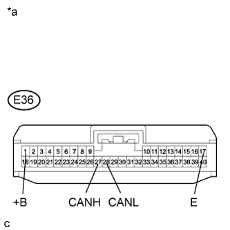
| CERTIFICATION ECU (w/ Smart Key System) |
Disconnect the connector from the certification ECU.
Text in Illustration *a Front view of wire harness connector
(to Certification ECU)Measure the resistance according to the value(s) in the table below.
- Standard Resistance:
Terminal No. (Symbol) Wiring Color Condition Specified Condition E36-27 (CANH) - E36-28 (CANL) SB - W Ignition switch off 54 to 69 Ω E36-27 (CANH) - E36-17 (E) SB - W-B Ignition switch off 200 Ω or higher E36-28 (CANL) - E36-17 (E) W - W-B Ignition switch off 200 Ω or higher E36-27 (CANH) - E36-1 (+B) SB - GR Cable is disconnected from negative (-) battery terminal 6 kΩ or higher E36-28 (CANL) - E36-1 (+B) W - GR Cable is disconnected from negative (-) battery terminal 6 kΩ or higher
 |
| MAIN BODY ECU (w/ Smart Key System) |
Disconnect the connector from the main body ECU.
Measure the resistance according to the value(s) in the table below.
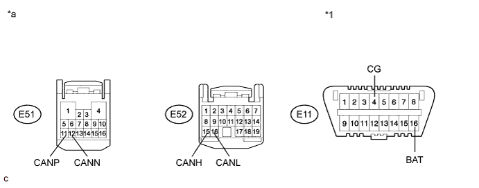
Text in Illustration *1 DLC3 - - *a Front view of wire harness connector
(to Main Body ECU)- - - Standard Resistance:
Terminal No. (Symbol) Wiring Color Condition Specified Condition E52-15 (CANH) - E52-16 (CANL) R - W Ignition switch off 54 to 69 Ω E52-15 (CANH) - E11-4 (CG) R - W-B Ignition switch off 200 Ω or higher E52-16 (CANL) - E11-4 (CG) W - W-B Ignition switch off 200 Ω or higher E52-15 (CANH) - E11-16 (BAT) R - LG Cable is disconnected from negative (-) battery terminal 6 kΩ or higher E52-16 (CANL) - E11-16 (BAT) W - LG Cable is disconnected from negative (-) battery terminal 6 kΩ or higher E51-11 (CANP) - E51-12 (CANN) R - W Ignition switch off 108 to 132 Ω E51-11 (CANP) - E11-4 (CG) R - W-B Ignition switch off 200 Ω or higher E51-12 (CANN) - E11-4 (CG) W - W-B Ignition switch off 200 Ω or higher E51-11 (CANP) - E11-16 (BAT) R - LG Cable is disconnected from negative (-) battery terminal 6 kΩ or higher E51-12 (CANN) - E11-16 (BAT) W - LG Cable is disconnected from negative (-) battery terminal 6 kΩ or higher
| MAIN BODY ECU (w/o Smart Key System) |
Disconnect the connector from the main body ECU.
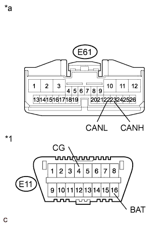
Text in Illustration *1 DLC3 *a Front view of wire harness connector
(to Main Body ECU)Measure the resistance according to the value(s) in the table below.
- Standard Resistance:
Terminal No. (Symbol) Wiring Color Condition Specified Condition E61-23 (CANH) - E61-22 (CANL) R - W Ignition switch off 54 to 69 Ω E61-23 (CANH) - E11-4 (CG) R - W-B Ignition switch off 200 Ω or higher E61-22 (CANL) - E11-4 (CG) W - W-B Ignition switch off 200 Ω or higher E61-23 (CANH) - E11-16 (BAT) R - G*1
R - LG*2Cable is disconnected from negative (-) battery terminal 6 kΩ or higher E61-22 (CANL) - E11-16 (BAT) W - G*1
W - LG*2Cable is disconnected from negative (-) battery terminal 6 kΩ or higher
- *1: TMC made
- *2: except TMC made
 |
| POWER STEERING ECU |
Disconnect the power steering ECU connectors.
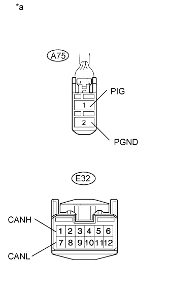
Text in Illustration *a Front view of wire harness connector
(to Power Steering ECU)Measure the resistance according to the value(s) in the table below.
- Standard Resistance:
Terminal No. (Symbol) Wiring Color Condition Specified Condition E32-1 (CANH) - E32-7 (CANL) SB - W Ignition switch off 54 to 69 Ω E32-1 (CANH) - A75-2 (PGND) SB - W-B Ignition switch off 200 Ω or higher E32-7 (CANL) - A75-2 (PGND) W - W-B Ignition switch off 200 Ω or higher E32-1 (CANH) - A75-1 (PIG) SB - L Cable is disconnected from negative (-) battery terminal 6 kΩ or higher E32-7 (CANL) - A75-1 (PIG) W - L Cable is disconnected from negative (-) battery terminal 6 kΩ or higher
 |
| ACCESSORY GATEWAY |
Disconnect the accessory gateway connector from the accessory.
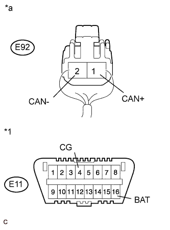
Text in Illustration *1 DLC3 *a Rear view of wire harness connector
(to Accessory Gateway)Measure the resistance according to the value(s) in the table below.
- Standard Resistance:
Terminal No. (Symbol) Wiring Color Condition Specified Condition E92-1 (CAN+) - E92-2 (CAN-) GR - W Ignition switch off 54 to 69 Ω E92-1 (CAN+) - E11-4 (CG) GR - W-B Ignition switch off 200 Ω or higher E92-2 (CAN-) - E11-4 (CG) W - W-B Ignition switch off 200 Ω or higher E92-1 (CAN+) - E11-16 (BAT) GR - G*1
GR - LG*2Cable is disconnected from negative (-) battery terminal 6 kΩ or higher E92-2 (CAN-) - E11-16 (BAT) W - G*1
W - LG*2Cable is disconnected from negative (-) battery terminal 6 kΩ or higher
*2: except TMC made
 |