AIRBAG SYSTEM (for TMMK Made) > VEHICLE CONTROL HISTORY |

for Preparation Click here
| Function Overview |
The vehicle control history is a function that records control data (record data) when triggered by specific vehicle behavior. When DTCs are not detected according to information provided by customers, by checking the vehicle control history, it is possible to gain a quantitative grasp on diagnostic information and the history can be used as a reference to proceed with malfunction diagnosis.
The vehicle control history is recorded in different storage areas designated by trigger group and it is possible to save up to 140 items in total. If storage space runs out, the data is cleared from the oldest data first for the respective storage area and new data is recorded.
Each trigger receives time information from the main body ECU (time elapsed since engine switch turned on (IG)) or the navigation system* (absolute time).
- *: Only for factory-installed navigation systems (factory option)
- *: Only for factory-installed navigation systems (factory option)
Data is recorded in the airbag sensor assembly EEPROM. Even if the battery negative terminal is disconnected, the vehicle control history does not disappear. Also, data cannot be cleared using the GTS.
| Notices for Use |
Vehicle control history is used as support information during malfunction diagnosis for each system and cannot be used to determine the actual cause of a problem.
Judgment of each trigger is based on signals from sensors and actuators (recognition value of each ECU). Therefore, make sure to inspect and adjust systems related to each trigger when using the vehicle control history.
Basic Flow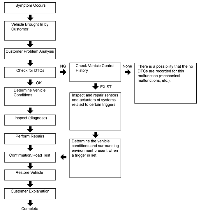
| Trigger Item |
Connect the GTS to the DLC3.
Turn the engine switch on (IG).
Using the GTS, enter the following menus: Body Electrical / SRS Airbag / Utility / Vehicle Control History.
Trigger Item Chart Related System Storage Area Group (storage limit) Trigger Item Name Trigger Description Remarks Engine control/Hybrid control/Automatic transmission Area 1
(Approximately 60 times)Accelerator pedal opening angle signal is high during low speed An accelerator high position signal condition continues for a certain period of time while in the low speed range. - Accelerator high position in mid to high speed An accelerator high position signal condition continues for a certain period of time while in the mid to high speed range. - Area 2
(Approximately 12 times)Accelerator pedal opening angle signal is high immediately after brake pedal is released An accelerator high position signal is received while in the low speed range after there is a change from brake input condition to brake and accelerator pedal released condition. - Area 3
(Approximately 40 times)Accelerator pedal opening angle is medium or higher immediately after shifting to R An accelerator mid to high position signal is received while in the low speed range immediately after the shift lever is moved to R during an accelerator low position signal condition. Excluding hybrid vehicles Accelerator pedal opening angle is medium or higher immediately after shifting to forward position An accelerator mid to high position signal is received while in the low speed range immediately after the shift lever is moved to a forward position (a position other than P, N or R) during an accelerator low position signal condition. Excluding hybrid vehicles Accelerator pedal opening angle is medium or higher immediately after shifting to driving position An accelerator mid to high position signal is received while in the low speed range immediately after the shift lever is moved to a driving position (a position other than P or N) during an accelerator low position signal condition. Only hybrid vehicles R position signal input during medium or higher accelerator signal input An accelerator mid to high position signal condition while the shift lever is in R continues for a certain period of time after the shift lever is moved to R during an accelerator mid to high position signal condition. Excluding hybrid vehicles Engine control/Hybrid control/Automatic transmission Area 3
(Approximately 40 times)Forward position signal input during medium or higher accelerator signal input An accelerator mid to high position signal condition continues for a certain period of time while in a forward position (a position other than P, N or R) after shifting to a forward position (a position other than P, N, or R) during an accelerator mid to high position signal condition. Excluding hybrid vehicles Driving position signal input during medium or higher accelerator signal input The shift lever is moved to a driving position (a position other than P or N) during an accelerator mid to high position signal condition. Only hybrid vehicles Accelerator signal and brake signal input simultaneously An accelerator mid to high position signal condition and brake input condition simultaneously continue for a certain period of time. - Medium or higher accelerator signal input immediately after switching to D or R The shift lever is moved to D (or R) during an accelerator low signal condition after the shift lever is moved to R (or D). After that, an accelerator mid to high position signal is received. - Medium or higher accelerator signal input during N An accelerator mid to high position signal is received while in a low speed range after the shift lever is moved to N. - Brake control Area 4
(Approximately 5 times)VSC operation history When VSC operation starts Only for vehicles with VSC TRC operation history When TRC operation starts Only for vehicles with TRC ABS operation history When ABS operation starts - Area 5
(Approximately 4 times)Sudden braking history Detects forward and backward acceleration above a certain level. Only for vehicles with VSC Sudden turning history Detects lateral acceleration above a certain level. Only for vehicles with VSC Pre-collision Area 6
(Approximately 4 times)PCS operation history (warning buzzer operation) PCS (warning buzzer) operates. Only for vehicles with PCS PCS operation history (warning brake operation) PCS (brake alarm) operates. Only for vehicles with PCS (w/ Driver Monitor Camera) PCS operation history (pre-collision brake assist operation) PCS (pre-crash safety brake assist) operates. Only for vehicles with PCS PCS operation history (prior brake operation) PCS (preliminary braking) operates. Only for vehicles with PCS PCS operation history (pre-collision brake operation) PCS (pre-crash safety brake) operates. Only for vehicles with PCS PCS actuation history (Pre-collision Seat Belt operated) PCS (pre-crash safety seat belt) operates. Only for vehicles with PCS PCS operation history (when acceleration above certain amount is detected) After PCS operates, forward and backward acceleration above a certain amount is detected. Only for vehicles with PCS Cruise control/Lane departure alert/Lane-keeping assist Torque sensor signal above certain amount is detected during LKA/LDA operation When the LKA/LDA system is ON, a torque sensor signal above a certain amount is detected. Only for vehicles with LKA/LDA (w/ Steering Control) Area 7
(Approximately 15 times)Accelerator pedal opening angle signal is high during cruise control operation An accelerator high position signal condition continues for a certain period of time during cruise control. Only for vehicles with cruise control
| Record Data Items |
When a trigger is detected, the vehicle status (ECU data) before and after the trigger are simultaneously recorded as record data.
Recording time and record data differ for each trigger.
When not "PCS Operation History"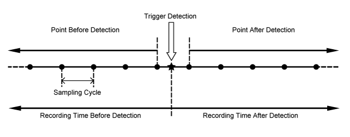
When "PCS Operation History"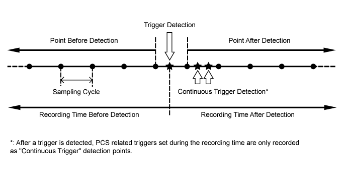
Record Data Record Specifications Trigger Item Record Data Before Detection After Detection Sampling
Cycle (sec.)ID No. Item Recording
Time (sec.)Number of Points Recording Time (sec.) Number of Points 2 Accelerator pedal opening angle signal is high during low speed 7.5 15 7.5 16 0.5 3 Accelerator high position in mid to high speed 7.5 15 7.5 16 0.5 4 Accelerator pedal opening angle signal is high immediately after brake pedal is released 7.5 15 7.5 16 0.5 5-1 Accelerator pedal opening angle is medium or higher immediately after shifting to R 5 10 5 11 0.5 5-2 Accelerator pedal opening angle is medium or higher immediately after shifting to forward position 5-3 Accelerator pedal opening angle is medium or higher immediately after shifting to driving position 6-1 R position signal input during medium or higher accelerator signal input 5 10 5 11 0.5 6-2 Forward position signal input during medium or higher accelerator signal input 6-3 Driving position signal input during medium or higher accelerator signal input 8 Accelerator signal and brake signal input simultaneously 5 10 5 11 0.5 9 Medium or higher accelerator signal input immediately after switching to D or R 5 10 5 11 0.5 10 Medium or higher accelerator signal input during N 5 10 5 11 0.5 12 VSC operation history 5 34 5 35 0.15 13 TRC operation history 5 34 5 35 0.15 14 ABS operation history 5 34 5 35 0.15 15 Sudden braking history 5 34 5 35 0.15 16 Sudden turning history 5 34 5 35 0.15 17 Accelerator pedal opening angle signal is high during cruise control operation 5 10 5 11 0.5 18-1 PCS operation history (warning buzzer operation) 5 10 5 11 0.5 18-2 PCS operation history (warning brake operation) 18-3 PCS operation history (pre-collision brake assist operation) 18-4 PCS operation history (prior brake operation) 18-5 PCS operation history (pre-collision brake operation) 18-6 PCS operation history (pre-collision seat belt operation) 18-7 PCS operation history (when acceleration above certain amount is detected) 19 Torque sensor signal above certain amount is detected during LKA/LDA operation 8 40 0 1 0.2 Record Data Chart Item Name Trigger ID No. Vehicle Speed 2, 3, 4, 5-1, 5-2, 5-3, 6-1, 6-2, 6-3, 8, 9, 10, 12, 13, 14, 15, 16, 17, 18-1, 18-2, 18-3, 18-4, 18-5, 18-6, 18-7, 19 Accelerator Opening Ratio 2, 3, 4, 5-1, 5-2, 5-3, 6-1, 6-2, 6-3, 8, 9, 10, 12, 13, 14, 15, 16, 17, 18-1, 18-2, 18-3, 18-4, 18-5, 18-6, 18-7, 19 Engine RPM Data 2, 3, 4, 5-1, 5-2, 5-3, 6-1, 6-2, 6-3, 8, 9, 10, 12, 13, 14, 15, 16, 17, 18-1, 18-2, 18-3, 18-4, 18-5, 18-6, 18-7, 19 Cruise Control 2, 3, 4, 5-1, 5-2, 5-3, 6-1, 6-2, 6-3, 8, 9, 10, 12, 13, 14, 15, 16, 17, 18-1, 18-2, 18-3, 18-4, 18-5, 18-6, 18-7, 19 Shift Position Signal 2, 3, 4, 5-1, 5-2, 5-3, 6-1, 6-2, 6-3, 8, 9, 10, 12, 13, 14, 15, 16, 17, 18-1, 18-2, 18-3, 18-4, 18-5, 18-6, 18-7, 19 Brake SW 2, 3, 4, 5-1, 5-2, 5-3, 6-1, 6-2, 6-3, 8, 9, 10, 12, 13, 14, 15, 16, 17, 18-1, 18-2, 18-3, 18-4, 18-5, 18-6, 18-7, 19 Brake Oil Pressure 2, 3, 4, 5-1, 5-2, 5-3, 6-1, 6-2, 6-3, 8, 9, 10, 12, 13, 14, 15, 16, 17, 18-1, 18-2, 18-3, 18-4, 18-5, 18-6, 18-7, 19 Yaw Rate Sensor Signal 2, 3, 4, 5-1, 5-2, 5-3, 6-1, 6-2, 6-3, 8, 9, 10, 12, 13, 14, 15, 16, 17, 18-1, 18-2, 18-3, 18-4, 18-5, 18-6, 18-7, 19 Longitudinal G Sensor Signal 2, 3, 4, 5-1, 5-2, 5-3, 6-1, 6-2, 6-3, 8, 9, 10, 12, 13, 14, 15, 16, 17, 18-1, 18-2, 18-3, 18-4, 18-5, 18-6, 18-7, 19 Lateral G Sensor Signal 2, 3, 4, 5-1, 5-2, 5-3, 6-1, 6-2, 6-3, 8, 9, 10, 12, 13, 14, 15, 16, 17, 18-1, 18-2, 18-3, 18-4, 18-5, 18-6, 18-7, 19 Throttle Opening Ratio 2, 3, 4, 5-1, 5-2, 5-3, 6-1, 6-2, 6-3, 8, 9, 10, 12, 13, 14, 15, 16, 17, 18-1, 18-2, 18-3, 18-4, 18-5, 18-6, 18-7, 19 Command Value of Fuel Injection Amount 2, 3, 4, 5-1, 5-2, 5-3, 6-1, 6-2, 6-3, 8, 9, 10, 12, 13, 14, 15, 16, 17, 18-1, 18-2, 18-3, 18-4, 18-5, 18-6, 18-7, 19 Steering Signal 2, 3, 4, 5-1, 5-2, 5-3, 6-1, 6-2, 6-3, 8, 9, 10, 12, 13, 14, 15, 16, 17, 18-1, 18-2, 18-3, 18-4, 18-5, 18-6, 18-7, 19 HV Recognition Flag 2, 3, 4, 5-1, 5-2, 5-3, 6-1, 6-2, 6-3, 8, 9, 10, 12, 13, 14, 15, 16, 17, 18-1, 18-2, 18-3, 18-4, 18-5, 18-6, 18-7, 19 Diesel Flag 2, 3, 4, 5-1, 5-2, 5-3, 6-1, 6-2, 6-3, 8, 9, 10, 12, 13, 14, 15, 16, 17, 18-1, 18-2, 18-3, 18-4, 18-5, 18-6, 18-7, 19 Sensor Type Identification (Security) 2, 3, 4, 5-1, 5-2, 5-3, 6-1, 6-2, 6-3, 8, 9, 10, 12, 13, 14, 15, 16, 17, 18-1, 18-2, 18-3, 18-4, 18-5, 18-6, 18-7, 19 Sensor Type Identification (G Sensor Layout) 2, 3, 4, 5-1, 5-2, 5-3, 6-1, 6-2, 6-3, 8, 9, 10, 12, 13, 14, 15, 16, 17, 18-1, 18-2, 18-3, 18-4, 18-5, 18-6, 18-7, 19 Sensor Type Identification (G Sensor) 2, 3, 4, 5-1, 5-2, 5-3, 6-1, 6-2, 6-3, 8, 9, 10, 12, 13, 14, 15, 16, 17, 18-1, 18-2, 18-3, 18-4, 18-5, 18-6, 18-7, 19 Sensor Type Identification (Yaw Rate Sensor) 2, 3, 4, 5-1, 5-2, 5-3, 6-1, 6-2, 6-3, 8, 9, 10, 12, 13, 14, 15, 16, 17, 18-1, 18-2, 18-3, 18-4, 18-5, 18-6, 18-7, 19 Yaw G Sensor Installation Information 2, 3, 4, 5-1, 5-2, 5-3, 6-1, 6-2, 6-3, 8, 9, 10, 12, 13, 14, 15, 16, 17, 18-1, 18-2, 18-3, 18-4, 18-5, 18-6, 18-7, 19 Shift Gear 2, 3, 4, 5-1, 5-2, 5-3, 6-1, 6-2, 6-3, 8, 9, 10, 12, 13, 15, 16 PWR Mode 2, 3, 4, 5-1, 5-2, 5-3, 6-1, 6-2, 6-3, 8, 9, 10, 12, 13, 15, 16 ECO Mode 2, 3, 4, 5-1, 5-2, 5-3, 6-1, 6-2, 6-3, 8, 9, 10, 12, 13, 15, 16 Integrated Sport Mode Indicator 2, 3, 4, 5-1, 5-2, 5-3, 6-1, 6-2, 6-3, 8, 9, 10, 12, 13, 15, 16 SNOW Mode 2, 3, 4, 5-1, 5-2, 5-3, 6-1, 6-2, 6-3, 8, 9, 10, 12, 13, 15, 16 Valid/Invalid of Driving Mode 2, 3, 4, 5-1, 5-2, 5-3, 6-1, 6-2, 6-3, 8, 9, 10, 12, 13, 15, 16 VSC OFF Lamp 2, 3, 4, 5-1, 5-2, 5-3, 6-1, 6-2, 6-3, 8, 9, 10, 12, 13, 15, 16 TRC OFF Lamp 2, 3, 4, 5-1, 5-2, 5-3, 6-1, 6-2, 6-3, 8, 9, 10, 12, 13, 15, 16 Valid/Invalid of TRC/VSC OFF Lamp 2, 3, 4, 5-1, 5-2, 5-3, 6-1, 6-2, 6-3, 8, 9, 10, 12, 13, 15, 16 EV Mode 2, 3, 4, 5-1, 5-2, 5-3, 6-1, 6-2, 6-3, 8, 9, 10, 12, 13, 15, 16 Valid/Invalid of EV Mode 2, 3, 4, 5-1, 5-2, 5-3, 6-1, 6-2, 6-3, 8, 9, 10, 12, 13, 15, 16 Integrated Sport Mode Signal 2, 3, 4, 5-1, 5-2, 5-3, 6-1, 6-2, 6-3, 8, 9, 10, 12, 13, 15, 16 Engine Load Factor 2, 3, 4, 5-1, 5-2, 5-3, 6-1, 6-2, 6-3, 8, 9, 10 READY Signal 2, 3, 4, 5-1, 5-2, 5-3, 6-1, 6-2, 6-3, 8, 9, 10, 12, 13, 15, 16 Gear Position Signal 2, 3, 4, 5-1, 5-2, 5-3, 6-1, 6-2, 6-3, 8, 9, 10, 15, 16 Turbine RPM/Input Shaft RPM 2, 3, 4, 5-1, 5-2, 5-3, 6-1, 6-2, 6-3, 8, 9, 10, 15, 16 Under VSC Control 12, 13, 14, 15, 16 Under ABS Control 12, 13, 14, 15, 16 Under VDM Control 12, 13, 14, 15, 16 Under TRC Operation Flag 12, 13, 14, 15, 16 FR Wheel Speed 12, 13, 14, 15, 16 FL Wheel Speed 12, 13, 14, 15, 16 RR Wheel Speed 12, 13, 14, 15, 16 RL Wheel Speed 12, 13, 14, 15, 16 Trigger Judgment Information 17, 19 Driving Force Demand Judgment Flag 17 DSS Judgment Flag 17 Cruise Control Res/ Accel SW 17 Cruise Control Set/ Coast SW 17 Cruise Control Cancel SW 17 Cruise Control Brake SW 17 Cruise Control D Signal 17 Cruise Control Main SW 17 Cruise Control Set Speed 17 Vehicle Speed (during Cruise Control) 17 Cruise Control Request Value 17 ACC Target Distance 17 ACC Target Condition 17 ACC Relative Speed 17 PCS Reception Data Invalid Flag 18-1, 18-2, 18-3, 18-4, 18-5, 18-6, 18-7 ALM Request Flag 18-1, 18-2, 18-3, 18-4, 18-5, 18-6, 18-7 ABK Request Flag 18-1, 18-2, 18-3, 18-4, 18-5, 18-6, 18-7 PBA Request Flag 18-1, 18-2, 18-3, 18-4, 18-5, 18-6, 18-7 FPB Request Flag 18-1, 18-2, 18-3, 18-4, 18-5, 18-6, 18-7 PB Request Flag 18-1, 18-2, 18-3, 18-4, 18-5, 18-6, 18-7 Extension Request Flag 18-1, 18-2, 18-3, 18-4, 18-5, 18-6, 18-7 PSB Request Flag 18-1, 18-2, 18-3, 18-4, 18-5, 18-6, 18-7 PCS READY Flag 18-1, 18-2, 18-3, 18-4, 18-5, 18-6, 18-7 PCS Display (PSB Communication) 18-1, 18-2, 18-3, 18-4, 18-5, 18-6, 18-7 PCS Display (System Fault) 18-1, 18-2, 18-3, 18-4, 18-5, 18-6, 18-7 PCS Display (Radar Dirt) 18-1, 18-2, 18-3, 18-4, 18-5, 18-6, 18-7 PCS Display (Temporarily not available) 18-1, 18-2, 18-3, 18-4, 18-5, 18-6, 18-7 Target Distance 18-1, 18-2, 18-3, 18-4, 18-5, 18-6, 18-7 Target Relative Velocity 18-1, 18-2, 18-3, 18-4, 18-5, 18-6, 18-7 Target Lateral Position 18-1, 18-2, 18-3, 18-4, 18-5, 18-6, 18-7 Target Number 18-1, 18-2, 18-3, 18-4, 18-5, 18-6, 18-7 Detection of Certain Level of Acceleration 18-1, 18-2, 18-3, 18-4, 18-5, 18-6, 18-7 LKA DDR Trigger Signal 19 Invalid of LKA DDR Data 19 Steering Wheel Release Condition 19 Steering Operation of LKA 19 Steering Operation of LDW 19 LKA Control Condition (EPS Control) 19 LKA Control Condition 19 Turn Signal Operation 19 EPS Torque Sensor Value 12, 13, 14, 15, 16, 19 Record Data Item Chart Item Name Item Explanation Displayed Value Remarks Vehicle Speed Displays the vehicle speed. 0 to 254 km/h - Accelerator Opening Ratio Displays the accelerator position sensor opening angle. 0 to 127% - Engine RPM Data Displays the engine speed. 0 to 25400 rpm - Cruise Control Displays whether the cruise control is operating. ON: Operating
OFF: Not operatingUnequipped vehicles display OFF. Shift Position Signal Displays the shift lever position. N / D / R / P / 5 / 4 / 3 / 2 / LO / B / SD / Sequential Mode / Not Specified - Brake SW Displays the stop light switch status. ON: Stop light illuminated
OFF: Not illuminated- Brake Oil Pressure Displays the fluid pressure inside the master cylinder. 0 to 12.192 MPa - Yaw Rate Sensor Signal Displays the angular velocity when turning. -61.488 to 61.488 deg/s Becomes a positive value when turning left. Longitudinal G Sensor Signal Displays the front and rear acceleration detected by the sensor. -9.04428 to 9.11606 - Acceleration becomes a positive value.
- Displays "INVALID" if below the smallest value.
Lateral G Sensor Signal Displays the right and left acceleration detected by the sensor. -9.04428 to 9.04428 Becomes a positive value when turning left. Throttle Opening Ratio Displays the engine throttle opening amount. 0 to 127% Only displayed except diesel vehicles ("INVALID" is displayed for other vehicles). Command Value of Fuel Injection Amount Displays the fuel injection volume (ECU command value). 0 to 127 mm3/st Only displayed for diesel vehicles. Steering Signal Displays the steering angle. -127 to 127 deg Becomes a positive value when turning left. HV Recognition Flag Displays whether the vehicle is a hybrid vehicle. HV: Hybrid vehicle
Other: Gasoline or diesel vehicle- Diesel Flag Displays whether the vehicle is a diesel vehicle. Diesel: Diesel vehicle
Other: Gasoline or hybrid vehicle- Sensor Type Identification (Security) Displays whether a clinometer sensor is installed. INSTALLED / NOT INSTALLED Displays a fixed value for each vehicle. Sensor Type Identification (G Sensor Layout) Displays the acceleration sensor position angle for the vehicle forward direction. 45° / 90° Displays a fixed value for each vehicle. Sensor Type Identification (G Sensor) Displays the number of acceleration sensors. 1 / 2 Displays a fixed value for each vehicle. Sensor Type Identification (Yaw Rate Sensor) Displays the number of yaw rate sensors. 1 / 2 Displays a fixed value for each vehicle. Yaw G Sensor Installation Information Displays normal direction or reverse direction (180° opposite) for the sensor position angle (acceleration sensor position angle). NORMAL DIRECTION / REVERSE DIRECTION Displays a fixed value for each vehicle. Shift Gear Displays the shift step (meter display value) when in sequential mode. OFF: Sequential mode off
GEARS 1 to 8: Shift step on meter display- PWR Mode Displays the PWR mode indicator light status. ON: PWR mode indicator light illuminated
OFF: PWR mode indicator light not illuminated- ECO Mode Displays the ECO mode indicator light status. ON: ECO mode indicator light illuminated
OFF: ECO mode indicator light not illuminated- Integrated Sport Mode Indicator Displays the SPORT mode indicator light status. ON: SPORT mode indicator light illuminated
OFF: SPORT mode indicator light not illuminated- SNOW Mode Displays the SNOW mode indicator light status. ON: SNOW mode indicator light illuminated
OFF: SNOW mode indicator light not illuminated- Valid/Invalid of Driving Mode Displays whether the driving mode information (PWR/ECO/SPORT/SNOW) is valid. VALID / INVALID - VSC OFF Lamp Displays the VSC OFF indicator light status. ON: VSC OFF indicator light illuminated
OFF: VSC OFF indicator light not illuminated- TRC OFF Lamp Displays the TRC OFF indicator light status. ON: TRC OFF indicator light illuminated
OFF: TRC OFF indicator light not illuminated- Valid/Invalid of TRC/VSC OFF Lamp Displays whether the TRC OFF indicator light and VSC OFF indicator light information is valid. VALID / INVALID - EV Mode Displays the EV mode indicator light status. ON: EV mode indicator light illuminated
OFF: EV mode indicator light not illuminated- Valid/Invalid of EV Mode Displays whether the EV mode information is valid. VALID / INVALID - Integrated Sport Mode Signal Displays SPORT mode status. NORMAL / ALL Sport / CHASSIS Sport / PWR Vehicles without integrated SPORT modes always display NORMAL. Engine Load Factor Displays the engine load. 0 to 158.75% Hybrid and diesel vehicles display "INVALID". READY Signal Displays whether driving is possible. ON / OFF Conventional and diesel vehicles display "INVALID". Gear Position Signal Displays the current gear step. 1 / 2 / 3 / 4 / 5 / 6 / 7 / 8 - Hybrid vehicles display "INVALID".
- CVT normally displays "1".
Turbine RPM/Input Shaft RPM Displays the torque converter output axis speed (input shaft speed). 0 to 12700 rpm - Under VSC Control Displays whether VSC control is operating. ON: Operating
OFF: Not operating or not equipped- Under ABS Control Displays whether ABS control is operating. ON: Operating
OFF: Not operating or not equipped- Under VDM Control Displays whether VDM control is operating. ON: Operating
OFF: Not operating or not equipped- Under TRC Operation Flag Displays whether TRC control is operating. ON: Operating
OFF: Not operating or not equipped- FR Wheel Speed Displays the front right wheel speed. -327.68 to 327.66 - FL Wheel Speed Displays the front left wheel speed. -327.68 to 327.66 - RR Wheel Speed Displays the rear right wheel speed. -327.68 to 327.66 - RL Wheel Speed Displays the rear left wheel speed. -327.68 to 327.66 - Trigger Judgment Information Displays whether cruise control related DTCs are displayed. DTCS DISPLAYED / DTCS NOT DISPLAYED - Driving Force Demand Judgment Flag Displays whether the drive power request method to the ECU is "Drive Power (N) Command" or another value. DRIVE POWER / NO DRIVE POWER Displays a fixed value for each vehicle. DSS Judgment Flag Displays whether a vehicle driving support system is installed. INSTALLED / NOT INSTALLED - Cruise Control Res/Accel SW Displays the cruise control RES/ACC switch status. ON / OFF - Cruise Control Set/Coast SW Displays the cruise control SET/COAST switch status. ON / OFF - Cruise Control Cancel SW Displays the cruise control CANCEL switch status. ON / OFF - Cruise Control Brake SW Displays the stop light switch status during cruise control. ON / OFF - Cruise Control D Signal Displays whether the shift position is D during cruise control. ON / OFF - Cruise Control Main SW Displays the cruise control main switch status. ON / OFF - Cruise Control Set Speed Displays the set vehicle speed for cruise control. 0 to 255 km/h - Vehicle Speed (during Cruise Control) Displays the vehicle speed during cruise control. 0 to 255 km/h - Cruise Control Request Value Displays the drive power requested by the cruise control system. -12800 to 12700 N - ACC Target Distance Displays the vehicle-to-vehicle distance to the preceding vehicle targeted by ACC (vehicle-to-vehicle distance mode). 0 to 252 m - ACC Target Condition Displays the ACC system control status. PRECEDING VEHICLE EXISTS / NO PRECEDING VEHICLE / FIXED SPEED MODE / RADAR MALFUNCTION - ACC Relative Speed Displays the relative vehicle speed of the preceding vehicle targeted by ACC (vehicle-to-vehicle distance mode). -128 to 127 km/h - PCS Reception Data Invalid Flag Displays the VALID/ INVALID status of PCS related data. VALID / INVALID - ALM Request Flag Displays whether an operation request was output to the warning function from PCS. ON: Operation request
OFF: No operation request- ABK Request Flag Displays whether an operation request was output to the warning brake function from PCS. ON: Operation request
OFF: No operation requestOnly displayed for vehicles with a driver monitor camera. PBA Request Flag Displays whether an operation request was output according to the pre-collision brake assist function from PCS. ON: Operation request
OFF: No operation request- FPB Request Flag Displays whether an operation request was output to the pre-collision function from PCS. ON: Operation request
OFF: No operation request- PB Request Flag Displays whether an operation request was output to the collision function from PCS. ON: Operation request
OFF: No operation request- Extension Request Flag Displays whether the PCS control target is the preceding vehicle. ON: Preceding vehicle
OFF: Not preceding vehicleA valid value is only displayed when the ALM, ABK, PBA, FPB and PB request flags are ON. Otherwise, OFF is displayed. PSB Request Flag Displays whether an operation request was output to the pre-collision seat belt control function from PCS. ON: Operation request
OFF: No operation request- PCS READY Flag Displays whether PCS is valid (operation permitted). VALID / INVALID - PCS Display (PSB Communication) Displays whether the pre-collision seat belt (PSB) communication is valid. COMMUNICATION VALID / COMMUNICATION INVALID - PCS Display (System Fault) Displays whether the PCS system is normal. SYSTEM NORMAL / SYSTEM MALFUNCTION - PCS Display (Radar Dirt) Displays whether the radar is normal. RADAR NORMAL / RADAR DIRTY - PCS Display (Temporarily not available) Displays whether the PCS system was temporarily unavailable. SYSTEM AVAILABLE / SYSTEM TEMPORARILY UNAVAILABLE - Target Distance Displays the PCS control target vehicle-to-vehicle distance. 0 to 163.83 m If a target is recognized, but PCS control is determined unnecessary, the largest value is displayed. Target Relative Velocity Displays the PCS control target vehicle relative speed. -51.175 to 0 m/s If a target is recognized, but PCS control is determined unnecessary, the largest value is displayed. Target Lateral Position Displays the PCS control target side position. -5.12 to 5.08 m - If a target is recognized, but PCS control is determined unnecessary, the largest value is displayed.
- If the target is on the right side of the vehicle a positive value is displayed, and if the target is on the left side a negative value is displayed.
Target Number Displays the target number determined by PCS control for targets recognized by the sensors (maximum 8 targets). 1 to 8 When the target number is 1 and the related record data (control target vehicle-to-vehicle distance, relative speed and side position) all display the largest values, PCS control has been determined unnecessary. Detection of Certain Level of Acceleration Displays whether acceleration above a certain level is detected. Unsupported / No / Invalid / Yes - LKA DDR Trigger Signal Displays whether the LKA/LDA trigger is set. TRIGGER OFF / TRIGGER CONDITION 1 / TRIGGER CONDITION 2 / TRIGGER CONDITION 3 - Invalid of LKA DDR Data Displays whether the LKA/LDA related information is valid. VALID / INVALID - Steering Wheel Release Condition Displays judgment status of steering hands during LKA control. ON: Released judged
OFF: Released not judged- Steering Operation of LKA Displays steering judgment status during LKA control. ON: Steering judged
OFF: Steering not judged- Steering Operation of LDW Displays steering judgment status during LDW (LDA) control. ON: Steering judged
OFF: Steering not judged- LKA Control Condition (EPS Control) Displays the EPS control (steering control) status. ON: Operating
OFF: Not operating- LKA Control Condition Displays the LKA/LDA control status. LKA AVAILABLE: LKA operation available
LDW AVAILABLE: LDW (LDA) operation available
OFF: Control operation unavailable- Turn Signal Operation Displays the turn signal operation status. OFF / RIGHT TURN ON / LEFT TURN ON - EPS Torque Sensor Value Displays the assist amount according to EPS. -12.8 to 127 Nm Becomes positive value when steering left. - Acceleration becomes a positive value.