UNLOCK WARNING SWITCH > REMOVAL |

for Preparation Click here
| 1. PRECAUTION (w/ Navigation System) |
- NOTICE:
- After the ignition switch is turned off, the navigation receiver assembly (HDD navigation system) records various types of memory and settings. As a result, after turning the ignition switch off, make sure to wait at least 60 seconds before disconnecting the cable from the negative (-) battery terminal.
| 2. PLACE FRONT WHEELS FACING STRAIGHT AHEAD |
| 3. DISCONNECT CABLE FROM NEGATIVE BATTERY TERMINAL |
- CAUTION:
- Wait for 90 seconds after disconnecting the cable to prevent airbag deployment (Click here).
| 4. REMOVE FRONT WHEEL LH |
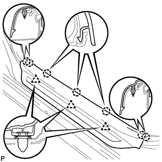
| 5. REMOVE FRONT DOOR SCUFF PLATE LH |
Disengage the 7 claws and 3 clips, and remove the front door scuff plate LH.
 |
| 6. REMOVE COWL SIDE TRIM SUB-ASSEMBLY LH |
Remove the cowl side trim clip.
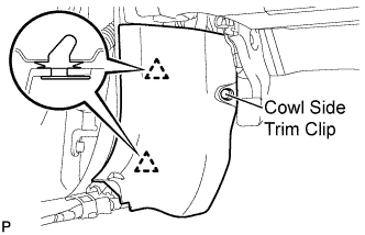 |
Disengage the 2 clips and remove the cowl side trim sub-assembly LH.
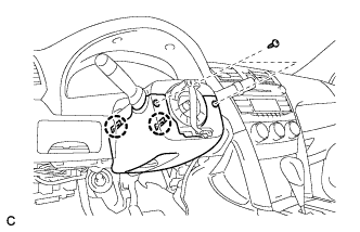
| 7. REMOVE LOWER INSTRUMENT PANEL FINISH PANEL LH |
Remove the bolt <A> and the screw <B>.
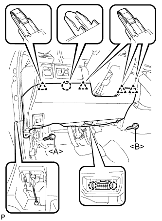 |
Disengage the 2 claws and the DLC3.
Disconnect the hood lock control cable assembly.
Disengage the claw and the 4 clips.
Remove the air hose, disconnect the connector, and then remove the lower instrument panel finish panel LH.
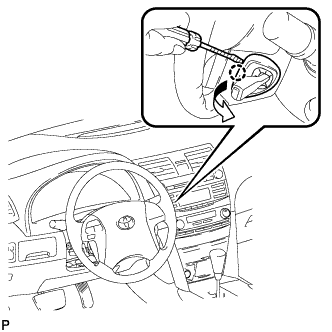
| 8. REMOVE LOWER NO. 2 STEERING WHEEL COVER |
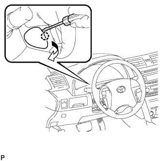
Using a screwdriver, disengage the claw and remove the No. 2 lower steering wheel cover.
- HINT:
- Tape up the screwdriver tip before use.
 |
| 9. REMOVE LOWER NO. 3 STEERING WHEEL COVER |
Using a screwdriver, disengage the claw and remove the No. 3 lower steering wheel cover.
- HINT:
- Tape up the screwdriver tip before use.
 |
| 10. REMOVE STEERING PAD |
Using a "TORX" socket (T30), loosen the 2 "TORX" screws until the groove along the screw circumference catches on the screw case.
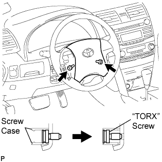 |
Pull out the steering pad from the steering wheel assembly and support the steering pad with one hand.
- NOTICE:
- When removing the steering pad, do not pull the airbag wire harness.
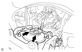 |
Disconnect the horn connector from the steering pad.
Disconnect the 2 airbag connectors and remove the steering pad.
- NOTICE:
- When handling the airbag connector, take care not to damage the airbag wire harness.
Remove the steering pad.
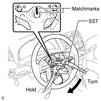
| 11. REMOVE STEERING WHEEL ASSEMBLY |
Remove the steering wheel assembly set nut.
Put matchmarks on the steering wheel assembly and the steering main shaft.
Disconnect the connectors from the spiral cable.
Using SST, remove the steering wheel assembly.
- SST
- 09950-50013
(09951-05010, 09952-05010, 09953-05020, 09954-05031)
 |
| 12. REMOVE STEERING COLUMN COVER |
Remove the 2 screws.
 |
Disengage the 2 claws to remove the lower steering column cover.
Disengage the claw to remove the upper steering column cover.
 |
| 13. REMOVE TURN SIGNAL SWITCH ASSEMBLY WITH SPIRAL CABLE SUB-ASSEMBLY |
Disconnect the connectors from the turn signal switch assembly with spiral cable sub-assembly.
Using pliers, grip the claws of the clamp and remove the turn signal switch assembly with spiral cable sub-assembly.
 |
| 14. REMOVE NO. 1 AIR DUCT |
Disengage the 2 claws and remove the No. 1 air duct.
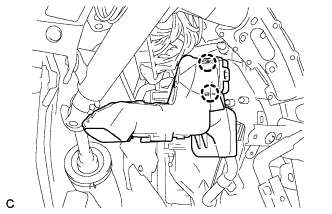 |
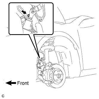
| 15. REMOVE STEERING COLUMN ASSEMBLY |
Remove the clamp from the steering column hole shield.
 |
Remove the bolt and slide the steering intermediate shaft assembly.
- NOTICE:
- Do not separate the steering intermediate shaft assembly from the power steering link assembly.
 |
Put matchmarks on the steering intermediate shaft assembly and the power steering link assembly.
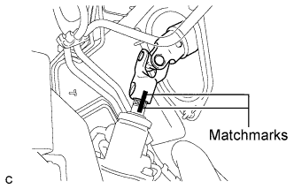 |
Separate the steering intermediate shaft assembly from the power steering link assembly.
Disconnect the connectors and wire harness clamps from the steering column assembly.
Remove the bolt, 2 nuts and the steering column assembly.
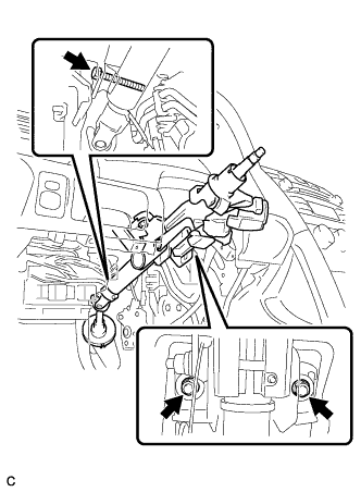 |
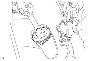
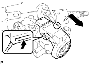
| 16. REMOVE TRANSPONDER KEY AMPLIFIER |
Using a screwdriver, widen the claws hanging onto the upper bracket by approximately 1.0 mm (0.039 in.).
Pull out the transponder key amplifier with the claw open.
- NOTICE:
- Using excessive force may damage the case.
 |
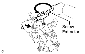
| 17. REMOVE STEERING COLUMN UPPER WITH SWITCH BRACKET ASSEMBLY |
Secure the steering column assembly in a vise.
Using a center punch, mark the center of the 2 tapered-head bolts.
Using a 3 to 4 mm (0.12 to 0.16 in.) diameter drill bit, drill a hole in the 2 tapered-head bolts.
Using a screw extractor, remove the 2 tapered-head bolts, and then remove the steering column upper with switch bracket assembly and the steering lock bracket from the steering column assembly.
 |
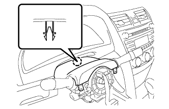
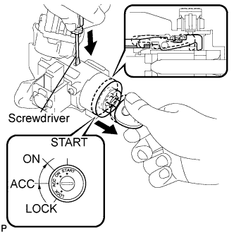
| 18. REMOVE IGNITION SWITCH LOCK CYLINDER ASSEMBLY |
Turn the ignition switch lock cylinder assembly to the ACC position.
Insert a screwdriver into the hole of the steering column upper with switch bracket assembly as shown in the illustration. Pull the ignition switch lock cylinder assembly until its claw contacts the stopper of the steering column upper with switch bracket assembly.
- NOTICE:
- Make sure to pull the ignition switch lock cylinder assembly until its claw contacts the stopper of the steering column upper with switch bracket assembly. Failure to do so will affect later work operations.
 |
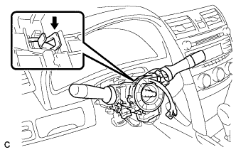
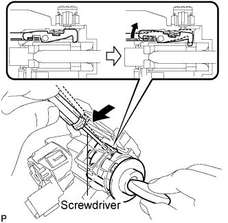
Insert a screwdriver into the hole of the steering column upper with switch bracket assembly. Push the screwdriver downward as shown in the illustration to disengage the claw of the ignition switch lock cylinder assembly, and pull out the ignition switch lock cylinder assembly.
 |
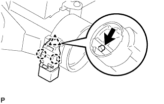
| 19. REMOVE UNLOCK WARNING SWITCH ASSEMBLY |
Remove the unlock warning switch assembly by pushing up the center part and releasing the 2 claws.
 |