PARKING BRAKE PEDAL > REMOVAL |

for Preparation Click here
| 1. PRECAUTION |
| 2. DISCONNECT CABLE FROM NEGATIVE BATTERY TERMINAL |
- CAUTION:
- Wait for 90 seconds after disconnecting the cable to prevent airbag deployment. (Click here)
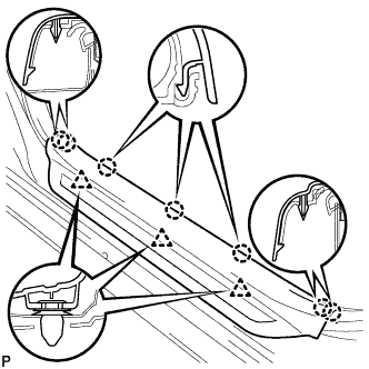
| 3. REMOVE FRONT DOOR SCUFF PLATE LH |
Disengage the 7 claws and 3 clips, and remove the front door scuff plate LH.
 |
| 4. REMOVE COWL SIDE TRIM SUB-ASSEMBLY LH |
Remove the cowl side trim clip.
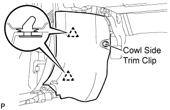 |
Disengage the 2 clips and remove the cowl side trim sub-assembly LH.
| 5. REMOVE FRONT DOOR SCUFF PLATE RH |
- HINT:
- Use the same procedures for the RH side and the LH side.
| 6. REMOVE COWL SIDE TRIM SUB-ASSEMBLY RH |
- HINT:
- Use the same procedures for the RH side and the LH side.
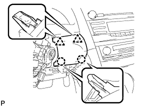
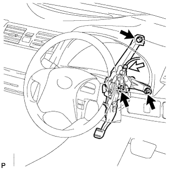
| 7. REMOVE LOWER INSTRUMENT PANEL FINISH PANEL LH |
Remove the bolt <A> and the screw <B>.
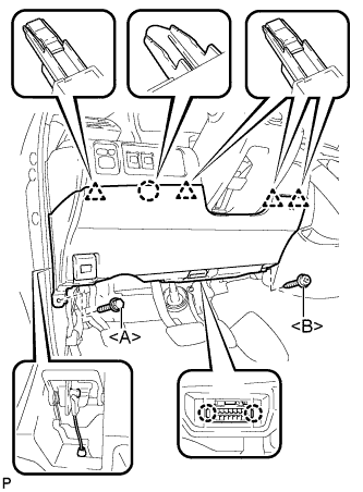 |
Disengage the 2 claws and the DLC3.
Disconnect the hood lock control cable assembly.
Disengage the claw and the 4 clips.
Remove the air hose, disconnect the connector, and then remove the lower instrument panel finish panel LH.
| 8. REMOVE NO. 1 INSTRUMENT PANEL SUB-ASSEMBLY (for RHD) |
Disengage the 3 claws and the 2 clips.
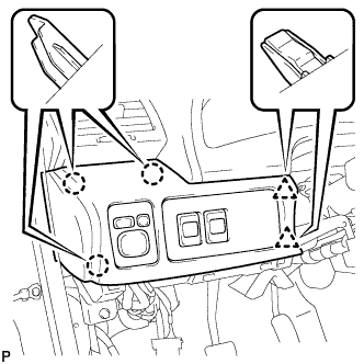 |
Disconnect each connector and remove the instrument panel sub-assembly.
| 9. REMOVE LOWER INSTRUMENT PANEL FINISH PANEL (for RHD) |
Disengage the 2 claws and 2 clips, and then remove the lower instrument panel finish panel.
 |
| 10. REMOVE INSTRUMENT CLUSTER FINISH PANEL NO.1 (for RHD) |
Remove the 2 clips.
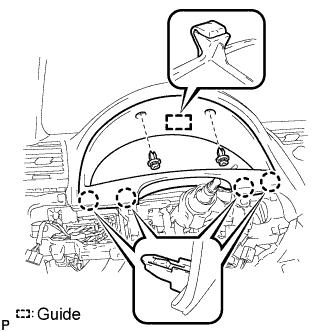 |
Disengage the guide and 4 claws and then remove the instrument cluster finish panel.
| 11. REMOVE COMBINATION METER ASSEMBLY (for RHD) |
Remove the 4 screws <E>.
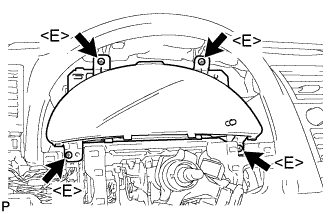 |
Disconnect each connector and remove the combination meter assembly.
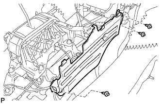
| 12. REMOVE INSTRUMENT PANEL NO. 2 UNDER COVER SUB-ASSEMBLY |
Disengage the 4 claws.
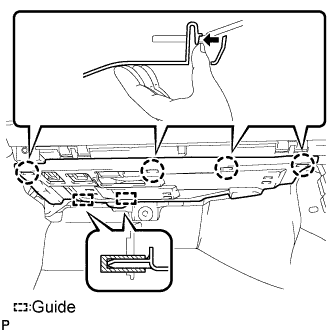 |
Disengage the 2 guides and remove the No. 2 under cover sub-assembly.
| 13. REMOVE LOWER INSTRUMENT PANEL SUB-ASSEMBLY |
Remove the bolt <A>.
Remove the 4 screws <B>.
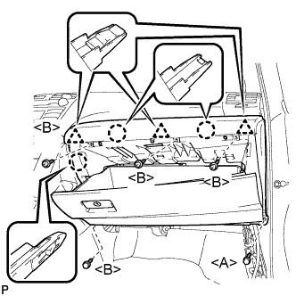 |
Disengage the 3 claws and 3 clips, and then remove the lower instrument panel sub-assembly.
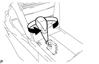
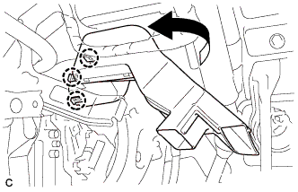
| 14. REMOVE SHIFT LEVER KNOB SUB-ASSEMBLY |
Turn the shift lever knob counterclockwise and remove the shift lever knob sub-assembly.
 |
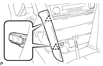
| 15. REMOVE NO. 1 INSTRUMENT CLUSTER FINISH PANEL GARNISH |
Disengage the 2 clips and remove the No. 1 instrument cluster finish panel garnish.
 |
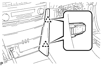
| 16. REMOVE NO. 2 INSTRUMENT CLUSTER FINISH PANEL GARNISH |
Disengage the 2 clips and remove the No. 2 instrument cluster finish panel garnish.
 |
| 17. REMOVE FLOOR SHIFT POSITION INDICATOR HOUSING SUB-ASSEMBLY |
Disengage the 6 claws and the 3 clips, and then remove the floor shift position indicator housing sub-assembly.
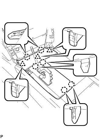 |
with Seat Heater System:
Disconnect each connector.
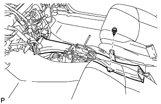
| 18. REMOVE UPPER CONSOLE REAR PANEL SUB-ASSEMBLY |
Disengage the 3 claws and the 5 clips.
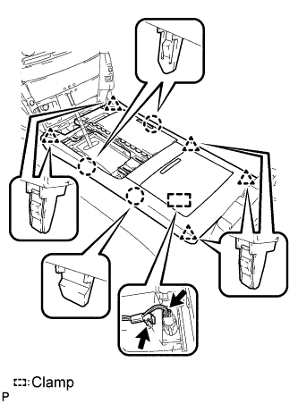 |
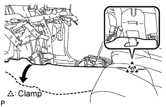
Disengage the clamp.
Disconnect the connector and remove the upper console rear panel sub-assembly.
| 19. REMOVE LOWER INSTRUMENT CLUSTER FINISH PANEL CENTER SUB-ASSEMBLY |
Remove the 2 screws <F>.
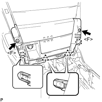 |
Disengage the 4 claws.
Disconnect each connector and remove the instrument cluster finish panel center sub-assembly.
- HINT:
- Set the shift lever in the D position.
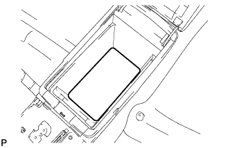
| 20. REMOVE CONSOLE BOX POCKET |
Remove the console box pocket.
| 21. REMOVE CONSOLE BOX CARPET |
Remove the console box carpet.
 |
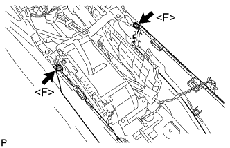
| 22. REMOVE CONSOLE BOX ASSEMBLY |
Remove the 2 screws <F>.
 |
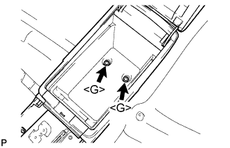
Remove the 2 bolts <G> and the console box assembly.
 |
| 23. REMOVE NO. 2 CONSOLE BOX INSERT FRONT |
Remove the 3 screws <F>.
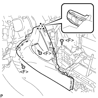 |
Disengage the clip and remove the No. 2 console box insert front.
| 24. REMOVE NO. 1 CONSOLE BOX INSERT FRONT |
Remove the 3 screws <F>.
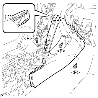 |
Disengage the clip and remove the No. 1 console box insert front.
| 25. REMOVE NO. 1 CONSOLE BOX DUCT (w/ Rear Register Duct) |
Remove the clip and No. 1 console box duct.
 |
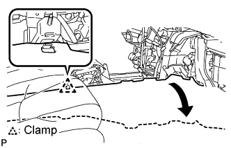
| 26. REMOVE FLOOR CARPET BRACKET LH |
Release the clamp.
 |
Turn back the floor carpet.
Remove the 3 clips.
 |
Remove the floor carpet bracket LH.
| 27. REMOVE FLOOR CARPET BRACKET RH |
Release the clamp.
 |
Turn back the floor carpet.
Remove the 3 clips.
 |
Remove the floor carpet bracket RH.
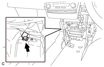
| 28. REMOVE YAW RATE AND ACCELERATION SENSOR (w/ VSC) |
Disconnect the yaw rate and acceleration sensor connector.
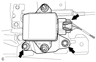 |
Remove the 2 bolts and yaw rate and acceleration sensor.
- NOTICE:
- Do not remove the yaw rate and acceleration sensor from the bracket.
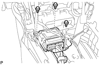
| 29. REMOVE FLOOR SHIFT LEVER ASSEMBLY |
Remove the 4 bolts and the floor shift lever assembly.
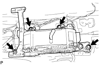 |
| 30. REMOVE CENTER AIRBAG SENSOR ASSEMBLY |
Turn back the carpet.
Disconnect the holder (with connectors).
 |
Remove the 3 bolts and center airbag sensor assembly.
| 31. DISCONNECT NO. 4 PARKING BRAKE CABLE ASSEMBLY |
Using a wrench, hold the lock nut and loosen the turnbuckle.
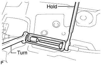 |
Disconnect the No. 4 parking brake cable assembly from the No. 1 parking brake cable assembly.
| 32. REMOVE PARKING BRAKE PEDAL ASSEMBLY (for LHD) |
Using needle-nose pliers, remove the clip from the No. 1 parking brake cable assembly.
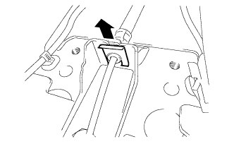 |
Remove the bolt, nut, and the No. 1 parking brake cable clamp.
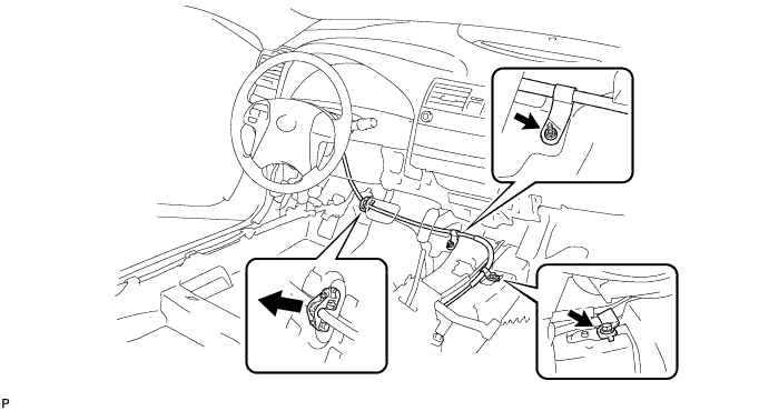
Separate the No. 1 parking brake cable assembly from the body.
Disconnect the parking brake switch connector.
 |
Remove the bolt, 2 nuts, and the parking brake pedal assembly with the No. 1 parking brake cable assembly from the body.
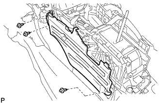
| 33. REMOVE NO. 1 AIR DUCT SUB-ASSEMBLY (for RHD) |
Disengage the 3 claws and remove the No. 1 air duct sub-assembly.
 |
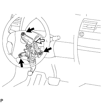
| 34. REMOVE PARKING BRAKE PEDAL ASSEMBLY (for RHD) |
Using needle-nose pliers, remove the clip from the No. 1 parking brake cable assembly.
|
Remove the bolt.
 |
Disconnect the parking brake switch connector.
 |
Remove the bolt, 2 nuts, and the parking brake pedal assembly with the No. 1 parking brake cable assembly from the body.