STEERING COLUMN ASSEMBLY (for Sedan) > INSTALLATION |

for Preparation Click here
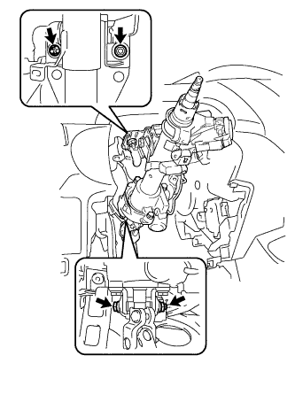
| 1. INSTALL STEERING COLUMN ASSEMBLY |
Install the steering column assembly onto the instrument panel reinforcement assembly with the bolt and 2 nuts.
- Torque:
- 25 N*m{ 255 kgf*cm , 18 ft.*lbf }
 |
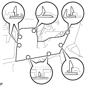
Connect all the connectors and clamp the wire harnesses onto the steering column assembly bracket.
| 2. INSTALL BRAKE PEDAL (for Automatic Transaxle) |
Apply MP grease No. 2 to the brake master cylinder push rod clevis pin and installation surfaces.
Install the 2 brake pedal bushes, and install the brake pedal with the nut and brake pedal shaft.
- Torque:
- 37 N*m{ 375 kgf*cm , 27 ft.*lbf }
Apply lithium soap base glycol grease to the brake master cylinder push rod clevis pin and installation surfaces.
 |
Connect the brake master cylinder push rod clevis to the brake pedal with the brake master cylinder push rod clevis pin, install the clip onto the brake master cylinder push rod clevis pin, and then install the brake pedal return spring.
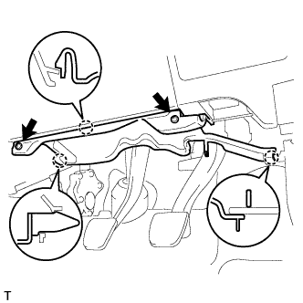
| 3. INSTALL BRAKE PEDAL SUPPORT (for Manual Transaxle) |
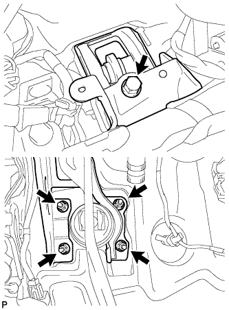 |
Install the pedal support with the bolt and 4 nuts.
- Torque:
- Bolt:
- 24 N*m{ 241 kgf*cm , 17 ft.*lbf }
- Nut:
- 9.0 N*m{ 92 kgf*cm , 80 in.*lbf }
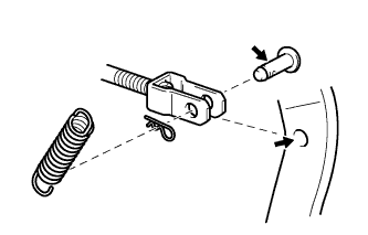
| 4. INSTALL BRAKE MASTER CYLINDER PUSH ROD CLEVIS (for Manual Transaxle) |
Apply lithium soap base glycol grease to the push rod pin.
Install the push rod clevis with the push rod pin and clip.
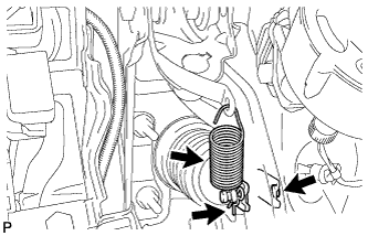 |
Install the brake pedal return spring.
| 5. INSTALL NO. 2 STEERING INTERMEDIATE SHAFT ASSEMBLY |
Connect all the connectors and clamp the wire harnesses onto the steering column assembly bracket.
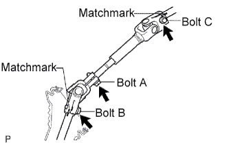 |
Align the matchmarks on steering intermediate shaft assembly No. 2 and the steering sliding yoke and provisionally install them with bolt C.
- Torque:
- 35 N*m{ 360 kgf*cm , 26 ft.*lbf }
Align the matchmarks on the steering sliding yoke and steering gear assembly and install them with bolt B.
- Torque:
- 35 N*m{ 360 kgf*cm , 26 ft.*lbf }
Tighten bolt A.
- Torque:
- 35 N*m{ 360 kgf*cm , 26 ft.*lbf }
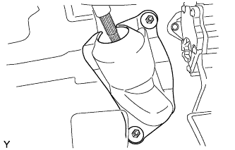
| 6. INSTALL COLUMN HOLE COVER SILENCER SHEET |
Install the column hole cover plate with the 2 clips.
 |
Install the floor carpet.
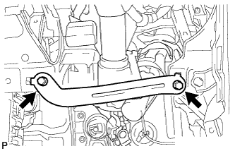
| 7. INSTALL INSTRUMENT PANEL SUB REINFORCEMENT |
Align the 2 claws and install the reinforcement instrument panel sub with the 2 bolts.
 |
| 8. INSTALL INSTRUMENT LOWER PANEL FINISH PANEL SUB-ASSEMBLY |
 |
Install the 2 <A> screws.
Engage the 7 claws and install the instrument panel lower finish panel.
 |
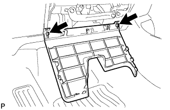
| 9. INSTALL INSTRUMENT PANEL UNDER COVER SUB-ASSEMBLY LH |
Engage the 3 claws and install the instrument panel under cover.
 |
Tighten the 2 screws.
| 10. INSTALL POWER STEERING ECU |
Connect the 2 steering column assembly connectors to the power steering ECU.
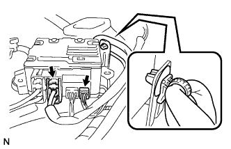 |
Install the power steering motor harness and torque sensor wire harness clamps onto the side of the power steering ECU.
Tilt the steering column assembly up and down to make sure that the power steering motor harness and torque sensor wire harness do not interfere with any components.
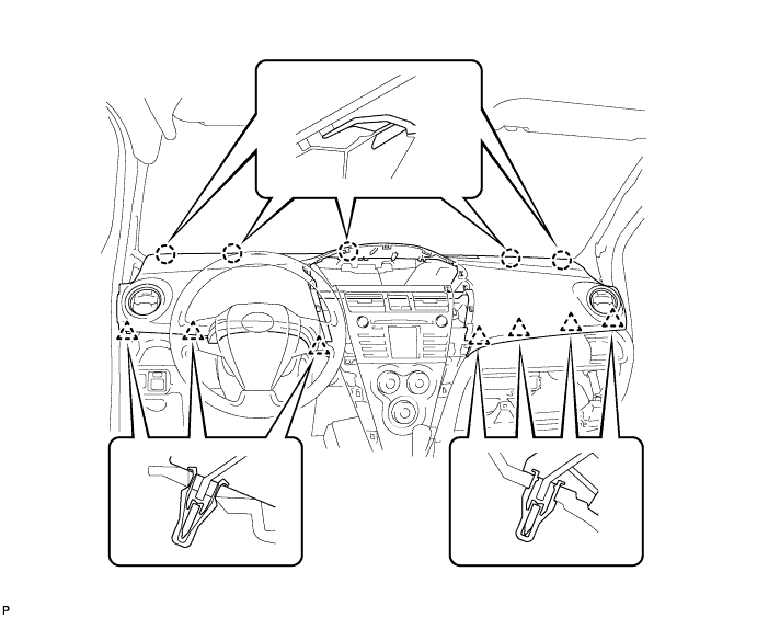
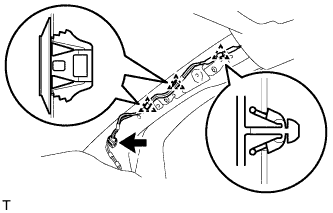
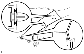
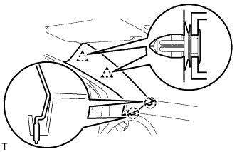
| 11. INSTALL UPPER INSTRUMENT PANEL SUB-ASSEMBLY |
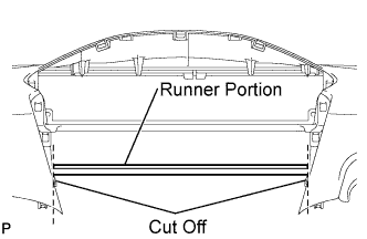 |
Using a nipper, cut off both ends of the runner portion shown in the illustration (When installing a new one).
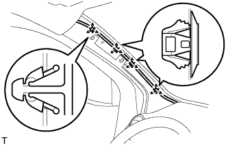
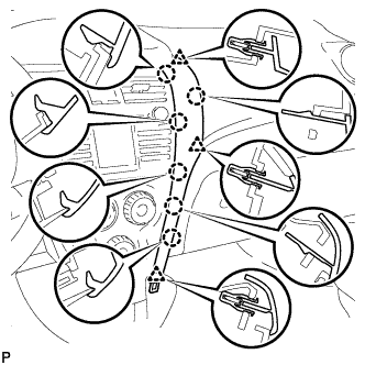
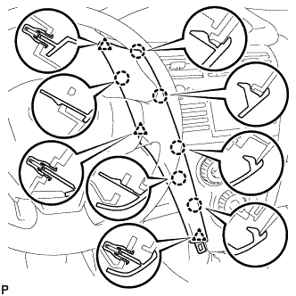
Engage the 5 claws at the front side of the instrument panel.
Engage the 7 clips at the rear side of the instrument panel.
Install the upper instrument panel with the 2 <C> bolts and the 2 <B> screws.
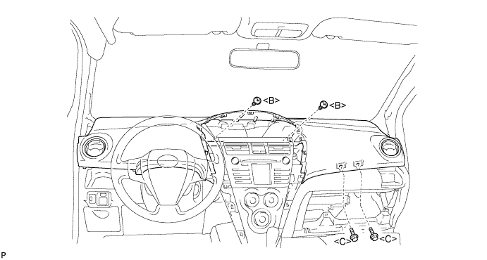
- Torque:
- 20 N*m{ 204 kgf*cm , 15 ft.*lbf } for bolt <C>
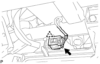
Connect the passenger airbag connector and clamp.
 |
| 12. INSTALL GLOVE COMPARTMENT DOOR ASSEMBLY |
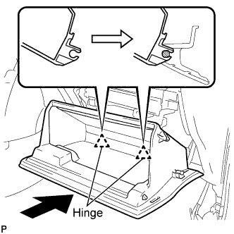 |
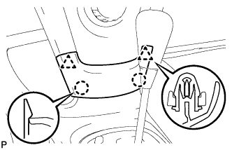
Engage the claws of the hinge portions by pushing the glove compartment door in the horizontal direction to install the glove compartment door assembly.
- NOTICE:
- Engage the claw by pushing it in the horizontal direction, otherwise, installation failure caused by excessive play around the hinge portion will result.
Slightly flex the upper portion of the glove compartment door assembly to engage the stopper.
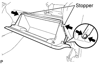 |
Install the 2 glove compartment door stoppers onto the glove compartment door.
| 13. INSTALL FRONT PILLAR GARNISH RH |
Install the 3 clamps.
 |
Connect the antenna connector.
Engage the 2 clips and the 2 claws and install the front pillar garnish.
 |
| 14. INSTALL FRONT PILLAR GARNISH LH |
Install the 4 clamps.
 |
Engage the 2 clips and the 2 claws and install the front pillar garnish.
 |
| 15. INSTALL FRONT DOOR OPENING TRIM WEATHERSTRIP RH |
Install the front door opening trim weatherstrip.
| 16. INSTALL FRONT DOOR OPENING TRIM WEATHERSTRIP LH |
Install the front door opening trim weatherstrip.
| 17. INSTALL COMBINATION METER ASSEMBLY |
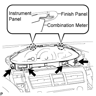 |
Install the combination meter assembly with the 2 screws.
- NOTICE:
- Install the meter by inserting the ribbed portions of the meter between the instrument panel and meter cluster.
Connect the 2 connectors.
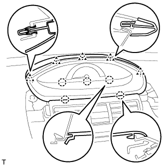
| 18. INSTALL NO. 1 INSTRUMENT CLUSTER FINISH PANEL |
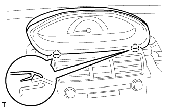 |
Fit the 2 claws of the instrument cluster finish panel into the upper instrument cluster finish panel center.
Engage the 5 claws and 5 clips and install the instrument cluster finish panel.
 |
| 19. INSTALL INSTRUMENT PANEL FINISH PANEL END RH |
 |
Engage the 6 claws and 3 clips and install the instrument panel finish panel end RH.
| 20. INSTALL INSTRUMENT PANEL FINISH PANEL END LH |
 |
Engage the 6 claws and 3 clips and install the instrument panel finish panel end LH.
| 21. INSTALL INSTRUMENT PANEL FINISH PANEL LOWER CENTER |
 |
Engage the 2 claws and 2 clips and install the instrument panel finish panel lower center.
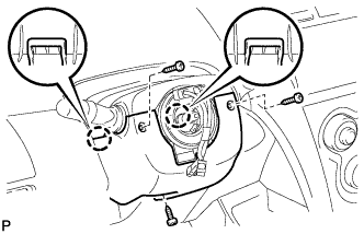
| 22. INSTALL COMBINATION SWITCH ASSEMBLY |
Install the combination switch assembly onto the steering column assembly with the clamp.
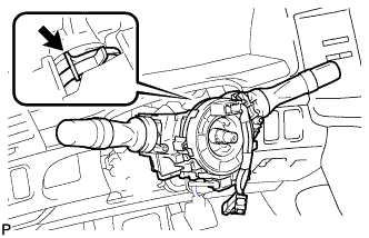 |
Connect all the connectors to the turn signal switch with spiral cable.
| 23. INSTALL STEERING COLUMN COVER |
Engage the claw to install the steering column upper cover.
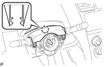 |
Engage the 2 claws to install the steering column lower cover.
 |
Install the 3 screws.
| 24. INSTALL STEERING WHEEL ASSEMBLY |
Align the matchmarks and install the steering wheel assembly onto the steering column assembly.
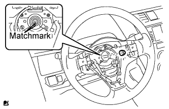 |
Install the nut.
- Torque:
- 50 N*m{ 510 kgf*cm , 37 ft.*lbf }
Connect all connectors to the spiral cable.
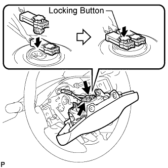
| 25. INSTALL STEERING PAD |
 |
- NOTICE:
- Do not use a steering pad that has been dropped.
Confirm that the ignition switch is turned to OFF.
Confirm that the negative battery terminal is detached.
- CAUTION:
- Do not begin the operation for at least 90 seconds after the negative battery terminal is detached.
Connect the horn terminal.
Connect the airbag connector.
- NOTICE:
- Match the color of the airbag connector with that of the steering pad assembly, and install the airbag connector.
- Securely lock the locking button.
Install the steering pad.
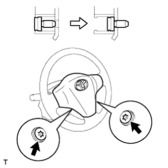 |
Using "Torx" socked wrench T30, tighten the 2 bolts.
- Torque:
- 8.8 N*m{ 90 kgf*cm , 78 in.*lbf }
- NOTICE:
- Tighten the 2 bolts while holding the steering pad to prevent it moving upward.
| 26. POSITION FRONT WHEELS FACING STRAIGHT AHEAD |
| 27. CHECK SRS WARNING LIGHT |
| 28. PERFORM CALIBRATION OF TORQUE SENSOR ZERO POINT |