ENGINE UNIT (for Hatchback) > REASSEMBLY |

for Preparation Click here
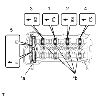
| 1. INSTALL STUD BOLT |
Using "TORX" socket wrench E5, install the 4 stud bolts.
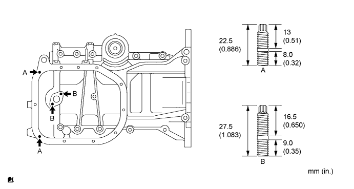
- Torque:
- 5.0 N*m{ 51 kgf*cm , 44 in.*lbf }
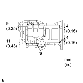
| 2. INSTALL OIL PAN SUB-ASSEMBLY |
Remove any old packing material from the contact surface.
Apply a continuous bead of seal packing (Diameter 2.0 to 3.0 mm (0.079 to 0.118 in.)) to the oil pan mating surface as shown in the illustration.
Text in Illustration *a Seal Packing - Seal packing:
- Toyota Genuine Seal Packing Black, Three Bond 1207B or equivalent
- NOTICE:
- Install the oil pan within 3 minutes of applying seal packing.
- Do not expose the seal to engine oil for at least 2 hours after the installation.
 |
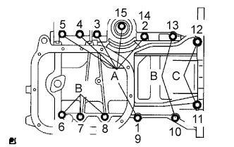
Install 2 new O-rings onto the cylinder block.
Using several steps, install and tighten the 13 bolts uniformly in the sequence shown in the illustration.
- Torque:
- 24 N*m{ 245 kgf*cm , 18 ft.*lbf }
- HINT:
Each bolt length is as follows:- Bolt A 49 mm (1.93 in.)
- Bolt B 88 mm (3.47 in.)
- Bolt C 144 mm (5.67 in.)
 |
| 3. INSTALL OIL STRAINER SUB-ASSEMBLY |
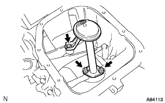 |
Install a new gasket and the oil strainer with the 2 nuts and the bolt.
- Torque:
- 16 N*m{ 163 kgf*cm , 12 ft.*lbf }
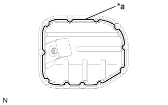
| 4. INSTALL NO. 2 OIL PAN SUB-ASSEMBLY |
Remove any old packing material from the contact surface.
Apply a continuous bead of seal packing (Diameter 2.5 to 3.5 mm (0.0984 to 0.1378 in.)) to the oil pan mating surface as shown in the illustration.
Text in Illustration *a Seal Packing - Seal packing:
- Toyota Genuine Seal Packing Black, Three Bond 1207B or equivalent
- NOTICE:
- Install the oil pan within 3 minutes of applying seal packing.
- Do not expose the seal to engine oil for at least 2 hours after the installation.
 |
Install the No. 2 oil pan with the 9 bolts and the 2 nuts.
- Torque:
- 9.0 N*m{ 92 kgf*cm , 80 in.*lbf }
Install the drain plug with a new gasket.
- Torque:
- 38 N*m{ 382 kgf*cm , 28 ft.*lbf }
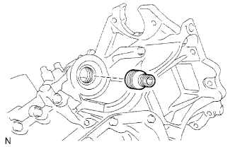
| 5. INSTALL OIL FILTER UNION |
Using a 12 mm hexagon wrench, install the oil filter union.
- Torque:
- 30 N*m{ 306 kgf*cm , 22 ft.*lbf }
 |
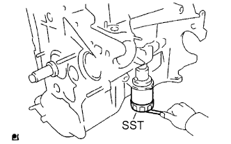
| 6. INSTALL OIL FILTER SUB-ASSEMBLY |
Check and clean the oil filter installation surface.
Apply clean engine oil to the gasket of a new oil filter.
Gently screw the oil filter into place, and tighten it until the gasket comes into contact with the seat.
Using SST, tighten it an additional 3/4 turn.
- SST
- 09228-06501
- HINT:
- When using a torque wrench, tighten it to the specified torque.
- Torque:
- 13 N*m{ 133 kgf*cm , 10 ft.*lbf }
 |
| 7. INSTALL CYLINDER HEAD GASKET |
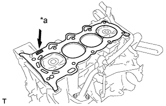 |
Place a new cylinder head gasket on the cylinder block with the Lot No. stamp facing upward.
Text in Illustration *a Lot No. - NOTICE:
- Remove any oil from the contact surfaces.
- Check the mounting orientation of the cylinder head gasket.
- Place the cylinder head on the cylinder head gently in order not to damage the gasket.
| 8. INSTALL CYLINDER HEAD SUB-ASSEMBLY |
- HINT:
- The cylinder head bolts are tightened in 2 successive steps.
- Perform "Inspection After Repairs" after replacing the cylinder head (Click here).
Apply a light coat of engine oil to the threads of the cylinder head bolts.
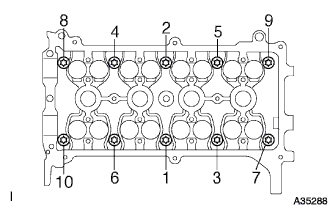
Using several steps, install and tighten the 10 cylinder head bolts and plate washers uniformly with an 8 mm bi-hexagon wrench, in the sequence shown in the illustration.
- Torque:
- 29 N*m{ 300 kgf*cm , 22 ft.*lbf }
 |
Mark the front of the cylinder head bolt with paint.
Retighten the cylinder head bolts 90° and then an additional by 90° as shown in the illustration.
Text in Illustration *a Paint Mark
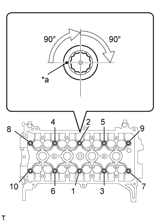 |
Check that the paint mark is now at a 180° angle from the front.
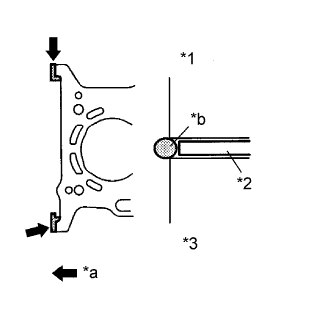
Apply a continuous bead of seal packing (Diameter 4.5 to 5.5 mm (0.177 to 0.217 in.)) as shown in the illustration.
- Seal Packing:
- Toyota Genuine Seal Packing Black, Three Bond 1207B or Equivalent
Text in Illustration *1 Cylinder Head *2 Cylinder Head Gasket *3 Cylinder Block *a Seal Packing *b Diameter: 4.5 to 5.5 mm - NOTICE:
- Remove any oil from the contact surfaces.
- Install the oil pump assembly within 3 minutes and tighten the bolts within 15 minutes of applying the seal packing.
 |
| 9. INSTALL REAR ENGINE OIL SEAL |
Apply MP grease to the lip of a new rear engine oil seal.
- NOTICE:
- Keep the lip free of foreign matter.
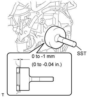
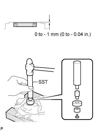
Using SST and a hammer, tap in the rear engine oil seal until its surface is flush with the cylinder block and oil pan.
- SST
- 09223-56010
- NOTICE:
- Do not tap the oil seal at an angle.
- Wipe any extra grease off the crankshaft.
 |
| 10. INSTALL CAMSHAFT TIMING GEAR ASSEMBLY |
- NOTICE:
- Install the camshaft timing gear assembly onto the camshaft with the lock pin of the camshaft timing gear assembly released.
- HINT:
- Perform "Inspection After Repairs" after replacing the camshaft timing gear assembly (Click here).
Clamp the camshaft in a vise, and confirm that it is locked.
- NOTICE:
- Do not damage the camshaft.
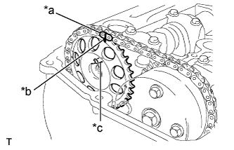
Put the camshaft timing gear assembly and camshaft together with the straight pin of the groove.
Text in Illustration *1 Straight Pin *a Groove
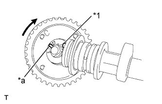 |
Turn the camshaft timing gear assembly clockwise while pushing it gently toward the camshaft. When the pin fits into the groove, push to ensure a good fit.
- NOTICE:
- Do not turn the camshaft timing gear in the retard direction (to the right).
Check that there is no clearance between the gear flange and the camshaft.
Tighten the bolt with the camshaft timing gear fixed.
- Torque:
- 64 N*m{ 653 kgf*cm , 47 ft.*lbf }
- NOTICE:
- Do not lock the camshaft timing gear assembly when tightening the bolt.
- Release the lock pin of the camshaft timing gear assembly first, and tighten the bolt when the lock pin is locked in the most retarded position.
- Tightening the bolts with the lock pin locked could cause breakage of the lock pin.
Check that the camshaft timing gear assembly can move in the retard direction (to the right) and is locked in the most retarded position.
| 11. INSTALL CAMSHAFT |
- HINT:
- Perform "Inspection After Repairs" after replacing the camshaft (Click here).
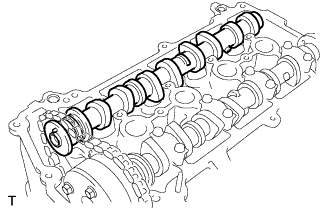
Apply a light coat of engine oil to the camshaft journals.
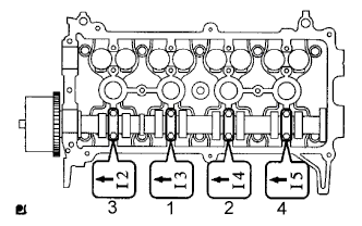
Place the camshaft on the cylinder head with the timing mark on the camshaft timing gear facing upward.
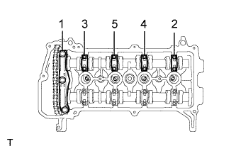
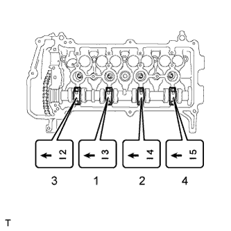
Examine the front marks and numbers and tighten the bolts in the sequence shown in the illustration.
- Torque:
- 13 N*m{ 129 kgf*cm , 9 ft.*lbf }
- NOTICE:
- Tighten each bolt uniformly while keeping the camshaft level.
 |
| 12. INSTALL CAMSHAFT TIMING SPROCKET |
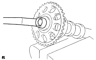
Clamp the camshaft in a vise, and confirm that it is locked.
- NOTICE:
- Do not damage the camshaft.
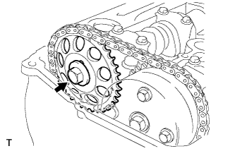
Align the knock pin hole the camshaft timing sprocket with the knock pin of the camshaft, and install the camshaft timing sprocket with the bolt.
- Torque:
- 64 N*m{ 653 kgf*cm , 47 ft.*lbf }
 |
| 13. INSTALL NO. 2 CAMSHAFT |
- HINT:
- Perform "Inspection After Repairs" after replacing the camshaft (Click here).
Apply a light coat of engine oil to the camshaft journals.
Place the camshaft on the cylinder head with the timing mark on the camshaft timing gear facing upward.
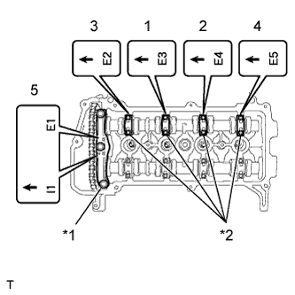
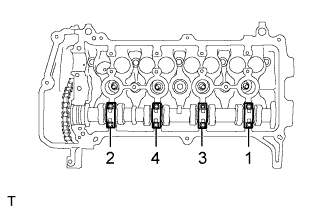
Examine the front marks and numbers on the No. 1 and No. 2 camshaft bearing caps and check that the order is as shown in the illustration. Then uniformly tighten the bolts, in several steps, in the sequence shown in the illustration.
Text in Illustration *1 No. 1 Bearing Cap *2 No. 2 Bearing Cap - Torque:
- No. 2 bearing cap:
- 13 N*m{ 129 kgf*cm , 9 ft.*lbf }
- No. 1 bearing cap:
- 23 N*m{ 235 kgf*cm , 17 ft.*lbf }
- NOTICE:
- Tighten each bolt uniformly while keeping the camshaft level.
 |
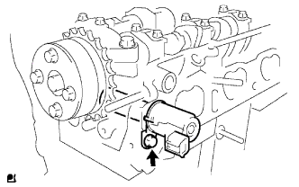
| 14. INSTALL CAMSHAFT POSITION SENSOR |
Apply engine oil to the O-ring.
- NOTICE:
- If the O-ring is damaged, replace the camshaft position sensor.
 |
Install the camshaft position sensor with the bolt.
- Torque:
- 8.0 N*m{ 82 kgf*cm , 71 in.*lbf }
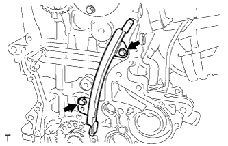
| 15. INSTALL NO. 1 CHAIN VIBRATION DAMPER |
Install the No. 1 chain vibration damper with the 2 bolts.
- Torque:
- 9.0 N*m{ 92 kgf*cm , 80 in.*lbf }
 |
| 16. INSTALL CHAIN SUB-ASSEMBLY |
Make sure that all the timing marks are in the positions (TDC) shown in the illustration.
Text in Illustration *a TDC *b Timing Mark - HINT:
- The positions of the timing marks may differ the predetermined positions due to the force of the valve spring.
 |
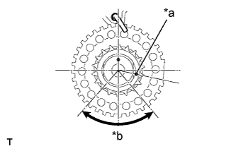
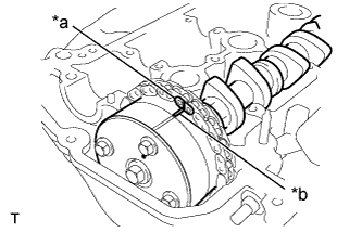
Set the timing mark of the crankshaft in a position between 40 and 140° ATDC, as illustrated.
Text in Illustration *a Timing Mark *b 40° to 140° ATDC
 |
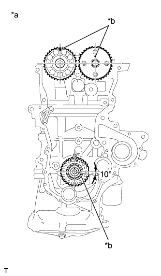
Set the camshaft timing gear and the camshaft timing sprocket in the positions (20° ATDC) shown in the illustration.
Text in Illustration *a 20° ATDC *b Timing Mark
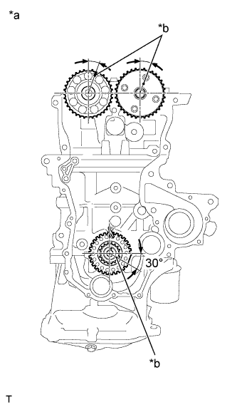 |
Set the crankshaft in the position (20° ATDC) shown in the illustration.
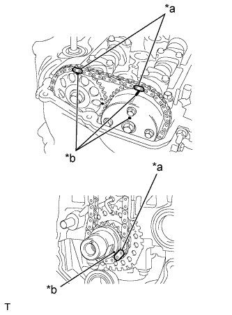
Align the timing marks of the camshaft with the mark plates of the timing chain and install the timing chain.
Text in Illustration *a Mark Plate *b Timing Mark - HINT:
- Align the timing marks with the mark plates while turning the hexagonal service portion of the camshaft using a wrench.
 |
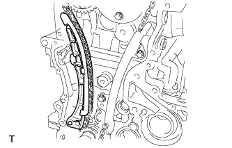
| 17. INSTALL CHAIN TENSIONER SLIPPER |
Install the chain tensioner slipper.
 |
| 18. INSTALL NO. 1 CHAIN TENSIONER ASSEMBLY |
Install the No. 1 chain tensioner assembly with the 2 bolts.
- Torque:
- 9.0 N*m{ 92 kgf*cm , 80 in.*lbf }
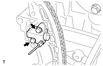 |
Remove the bar from the No. 1 chain tensioner assembly.
| 19. INSTALL OIL PUMP SEAL |
Using SST and a hammer, tap in a new oil pump seal until its surface is flush with the timing chain cover.
- SST
- 09950-60010
(09951-00250, 09951-00410, 09952-06010)
09950-70010 (09951-07100)
- NOTICE:
- Do not tap the oil seal at an angle.
- Keep the seal lip free of foreign matter.
 |
Apply a light coat of MP grease to the oil pump seal lip.
| 20. INSTALL OIL PUMP ASSEMBLY |
Install 2 new O-rings to the cylinder block sub-assembly and the oil pan sub-assembly.
Apply seal packing to the oil pump assembly, cylinder head sub-assembly and the cylinder block sub-assembly as shown in the illustration.
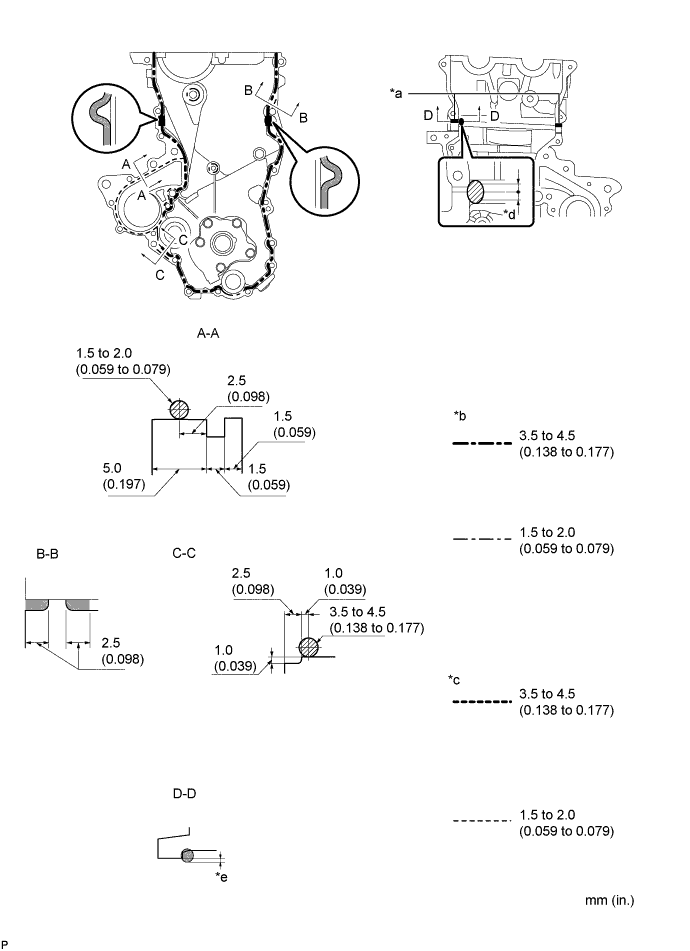
Text in Illustration *a Apply Seal Packing to the Inner Corners *b Seal Width (Other Part) *c Seal Width (Water Pump Part) *d Seal Packing Application Width 10 mm or more *e Apply enough seal packing so that it will protrude beyond the timing chain cover installation surface - - - Seal packing:
- Water pump part: Toyota Genuine Seal Packing 1282B, Three Bond 1282B or equivalent.
- Other part: Toyota Genuine Seal Packing Black, Three Bond 1207B or equivalent.
- NOTICE:
- Remove any oil from the contact surfaces.
- Install the oil pump assembly within 3 minutes and tighten the bolts and nut within 15 minutes of applying seal packing.
- Do not expose the seal to engine oil for at least 2 hours after the installation.
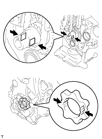
Align the keyway of the oil pump rotor with the rectangular portion of the crankshaft, and slide the oil pump into place.
 |
Temporarily install the oil pump assembly with the 16 bolts and the nut.
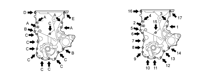
- NOTICE:
- Do not apply oil to the bolt A.
- HINT:
- Each bolt length is as follows.
- A: 30 mm (1.181 in.)
- B: 35 mm (1.378 in.)
- C: 20 mm (0.787 in.)
- E: 14 to 20 mm (0.551 to 0.787 in.), Double ended bolt
Tighten the 16 bolts and nut in the sequence shown in the illustration.
- Torque:
- Bolt A:
- 41 N*m{ 418 kgf*cm , 30 ft.*lbf }
- Bolt B:
- 12 N*m{ 122 kgf*cm , 9 ft.*lbf }
- Bolt C:
- 12 N*m{ 122 kgf*cm , 9 ft.*lbf }
- Nut D:
- 24 N*m{ 245 kgf*cm , 18 ft.*lbf }
- Bolt E:
- 24 N*m{ 245 kgf*cm , 18 ft.*lbf }
- NOTICE:
- Be careful not to disturb the seal packing.
- After installing the oil pump assembly, install the transverse engine engine mounting bracket within 10 minutes.
| 21. INSTALL ENGINE WATER PUMP ASSEMBLY |
Install the water pump assembly through a new water pump gasket with the 3 bolts and 2 nuts.
- Torque:
- 12 N*m{ 122 kgf*cm , 9 ft.*lbf }
| 22. INSTALL TRANSVERSE ENGINE ENGINE MOUNTING BRACKET |
Install the transverse engine engine mounting bracket with the 4 bolts.
- Torque:
- 55 N*m{ 561 kgf*cm , 41 ft.*lbf }
| 23. INSTALL CRANKSHAFT DAMPER SUB-ASSEMBLY |
Align the pin hole in the crankshaft damper with the pin position and install the crankshaft damper.
Temporarily install the bolt.
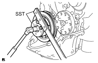
Using SST, tighten the bolt while holding the crankshaft damper.
- SST
- 09213-14010
(91651-60865)
09330-00021
- Torque:
- 128 N*m{ 1305 kgf*cm , 95 ft.*lbf }
- NOTICE:
- Check the SST installation positions when installing them, to avoid the SST fixing bolts from coming into contact with the oil pump.
 |
| 24. INSTALL WATER PUMP PULLEY |
Provisionally install the water pump pulley with the 3 bolts.
Using SST, hold the water pump pulley.
- SST
- 09960-10010
(09962-01000, 09963-00700)
Tighten the 3 bolts to the specified torque.
- Torque:
- 15 N*m{ 153 kgf*cm , 11 ft.*lbf }
| 25. INSPECT VALVE CLEARANCE |
- HINT:
- Inspect the valve clearance when the engine is cold.
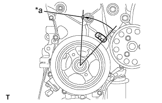
Set the No. 1 cylinder to TDC/compression.
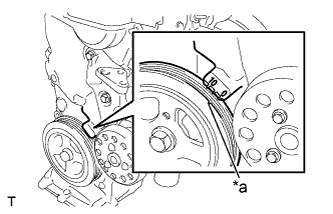
Turn the crankshaft damper and align its timing notch with the timing mark "0" of the oil pump.
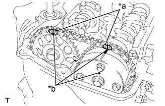
Text in Illustration *a Timing Notch Check that both timing marks on the camshaft timing sprocket and camshaft timing gear are facing upward, as shown in the illustration.
Text in Illustration *a Timing Marks - HINT:
- If not, turn the crankshaft 1 complete revolution (360°) and align the marks as above.

Check the valves indicated in the illustration.
Using a feeler gauge, measure the clearance between the valve lifter and camshaft.
- Valve clearance (cold):
- for intake:
- 0.15 to 0.25 mm (0.006 to 0.010 in.)
- for exhaust:
- 0.25 to 0.35 mm (0.010 to 0.014 in.)
Record any out-of-specification valve clearance measurements. They will be used later to determine the required replacement adjusting shim.
 |
Turn the crankshaft 1 complete revolution (360°) and align its timing notch with the timing mark "0" of the oil pump.
Check the valves indicated in the illustration.
Using a feeler gauge, measure the clearance between the valve lifter and camshaft.
- Valve clearance (cold):
- for intake:
- 0.15 to 0.25 mm (0.006 to 0.010 in.)
- for exhaust:
- 0.25 to 0.35 mm (0.010 to 0.014 in.)
Record any out-of-specification valve clearance measurements. They will be used later to determine the required replacement adjusting shim.
 |
| 26. ADJUST VALVE CLEARANCE |
 |
| *a | Matchmark |
- NOTICE:
- When rotating the camshaft with the timing chain removed, rotate the crankshaft damper counterclockwise 40° from the TDC and align its timing notch with the matchmark of the timing chain cover to prevent the pistons from coming into contact with the valves.
Remove the fan and generator V belt (Click here).
Remove the engine mounting insulator sub-assembly RH (Click here).
Set the No. 1 cylinder to TDC/compression.
Turn the crankshaft damper and align its timing notch with the timing mark "0" of the oil pump.
Text in Illustration *a Timing Notch Check that both timing marks on the camshaft timing sprocket and camshaft timing gear are facing upward, as shown in the illustration.
Text in Illustration *a Timing Marks - HINT:
- If not, turn the crankshaft 1 complete revolution (360°) and align the marks as above.

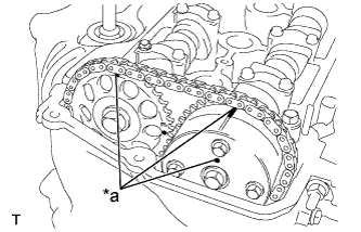
Place paint marks on the chain in the places where the timing marks of the camshaft timing sprocket and the camshaft timing gear are located.
Text in Illustration *a Paint Marks *b Timing Marks
 |
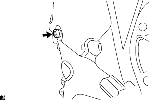
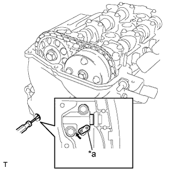
Using an 8 mm hexagon wrench, remove the screw plug.
 |
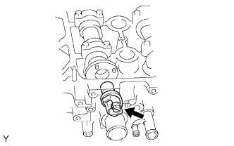
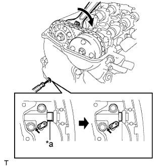
Insert a screwdriver into the service hole in the chain tensioner to pull the stopper plate of the chain tensioner upward.
Text in Illustration *a Stopper Plate
 |
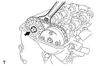
Using a wrench, rotate camshaft No. 2 clockwise to push in the plunger of the chain tensioner.
Text in Illustration *a Plunger
 |
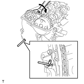
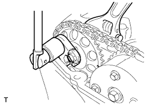
Remove the screwdriver from the service hole, then align the hole in the stopper plate with the service hole and insert a 3 mm (0.12 in.) diameter bar into the holes to hold the stopper plate.
- HINT:
- Fix the stopper plate using the bar while rotating the camshaft right and left slightly.
- Hold the bar with tape so that the bar does not come off.
 |
Using a wrench, hold the hexagonal lobe of camshaft No. 2 and remove the flange bolt.
 |
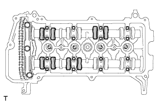
Using several steps, loosen and remove the 11 bearing cap bolts uniformly in the sequence shown in the illustration, then remove camshaft bearing cap No. 1 and camshaft bearing cap No. 2.
- NOTICE:
- Loosen each bolt uniformly while keeping the camshaft level.
 |
Remove the flange bolt and the camshaft timing sprocket.
 |
Remove No. 2 camshaft.
 |
Using several steps, loosen and remove the 8 bearing cap bolts uniformly in the sequence shown in the illustration, then remove No. 2 camshaft bearing cap.
- NOTICE:
- Loosen each bolt uniformly while keeping the camshaft level.
 |
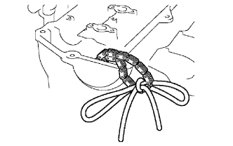
Hold the chain by hand and remove the camshaft and the camshaft timing gear assembly.
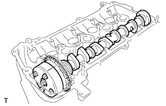 |
Tie the chain with a piece of string as shown in the illustration.
 |
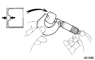
Remove the 16 valve lifters.
Using a micrometer, measure the thickness of the removed lifter.
 |
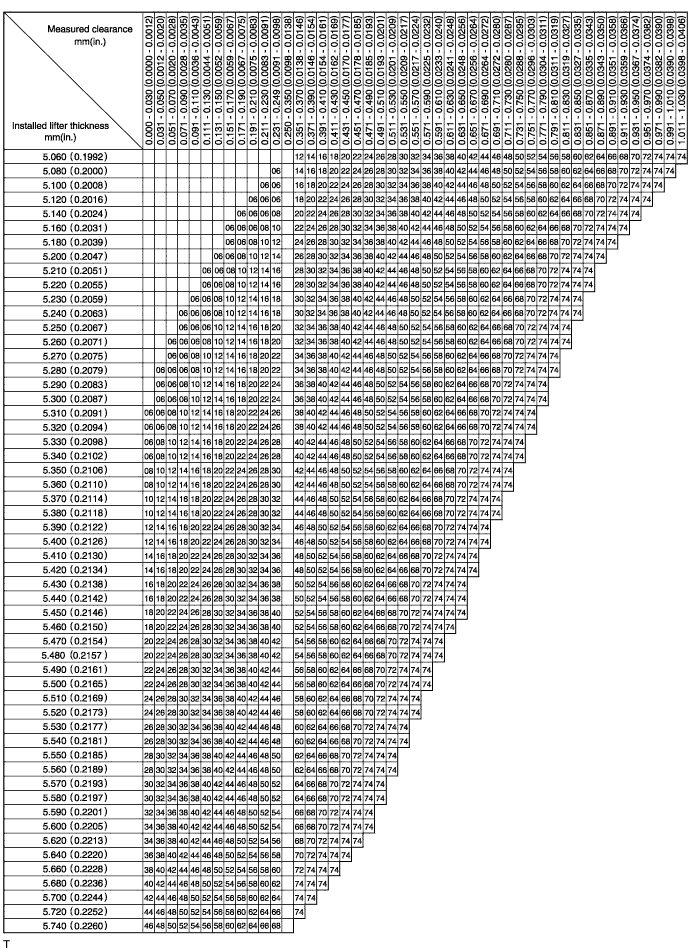
Calculate the thickness of a new lifter so that the valve clearance comes to within the specified values.
A Thickness of new lifter B Thickness of used lifter C Measured valve clearance - Valve clearance:
- Intake A = B + (C - 0.20 mm (0.008 in.))
- Exhaust A = B + (C - 0.30 mm (0.012 in.))
Select a new lifter with a thickness as close to the calculated values as possible.
- HINT:
- Lifters are available in 35 sizes in increments of 0.020 mm (0.0008 in.), from 5.060 mm (0.1992 in.) to 5.740 mm (0.2260 in.).
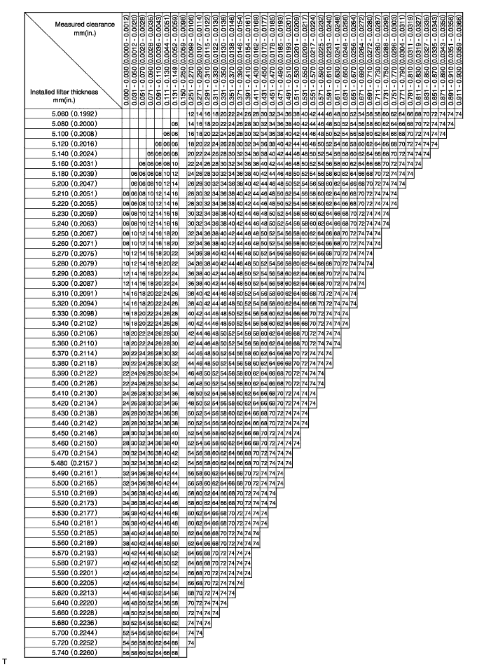
- Intake valve clearance (cold):
- 0.15 to 0.25 mm (0.006 to 0.010 in.)
- EXAMPLE:
- A 5.250 mm (0.2067 in.) lifter is installed, and the measured clearance is 0.400 mm (0.0158 in.). Replace the 5.250 mm (0.2067 in.) lifter with a new No. 46 lifter.
- New Shim Thickness:
Shim No. Thickness Shim No. Thickness Shim No. Thickness 06 5.060 (0.1992) 30 5.300 (0.2087) 54 5.540 (0.2181) 08 5.080 (0.2000) 32 5.320 (0.2094) 56 5.560 (0.2189) 10 5.100 (0.2008) 34 5.340 (0.2102) 58 5.580 (0.2197) 12 5.120 (0.2016) 36 5.360 (0.2110) 60 5.600 (0.2205) 14 5.140 (0.2024) 38 5.380 (0.2118) 62 5.620 (0.2213) 16 5.160 (0.2031) 40 5.400 (0.2126) 64 5.640 (0.2220) 18 5.180 (0.2039) 42 5.420 (0.2134) 66 5.660 (0.2228) 20 5.200 (0.2047) 44 5.440 (0.2142) 68 5.680 (0.2236) 22 5.220 (0.2055) 46 5.460 (0.2150) 70 5.700(0.2244) 24 5.240 (0.2063) 48 5.480 (0.2157) 72 5.720 (0.2252) 26 5.260 (0.2071) 50 5.500 (0.2165) 74 5.740 (0.2260) 28 5.280 (0.2079) 52 5.520 (0.2173)
- Exhaust valve clearance (Cold):
- 0.25 to 0.35 mm (0.010 to 0.014 in.)
- EXAMPLE:
- A 5.340 mm (0.2102 in.) lifter is installed, and the measured clearance is 0.440 mm (0.0173 in.). Replace the 5.340 mm (0.2102 in.) lifter with a new No. 48 lifter.
- New Shim Thickness:
Shim No. Thickness Shim No. Thickness Shim No. Thickness 06 5.060 (0.1992) 30 5.300 (0.2087) 54 5.540 (0.2181) 08 5.080 (0.2000) 32 5.320 (0.2094) 56 5.560 (0.2189) 10 5.100 (0.2008) 34 5.340 (0.2102) 58 5.580 (0.2197) 12 5.120 (0.2016) 36 5.360 (0.2110) 60 5.600 (0.2205) 14 5.140 (0.2024) 38 5.380 (0.2118) 62 5.620 (0.2213) 16 5.160 (0.2031) 40 5.400 (0.2126) 64 5.640 (0.2220) 18 5.180 (0.2039) 42 5.420 (0.2134) 66 5.660 (0.2228) 20 5.200 (0.2047) 44 5.440 (0.2142) 68 5.680 (0.2236) 22 5.220 (0.2055) 46 5.460 (0.2150) 70 5.700 (0.2244) 24 5.240 (0.2063) 48 5.480 (0.2157) 72 5.720 (0.2252) 26 5.260 (0.2071) 50 5.500 (0.2165) 74 5.740 (0.2260) 28 5.280 (0.2079) 52 5.520 (0.2173)
Install the selected valve lifter.
Apply a light coat of engine oil to the camshaft and camshaft journals.
Install the chain onto the camshaft timing gear with the paint mark and the timing mark aligned as shown in the illustration.
Text in Illustration *a Paint Mark *b Timing Mark
 |
Examine the front marks and the numbers on No. 2 camshaft bearing cap and check that the sequence is as shown in the illustration. Then uniformly tighten the bolts in several steps in the sequence shown in the illustration.
- Torque:
- 13 N*m{ 129 kgf*cm , 9.4 ft.*lbf }
- NOTICE:
- Tighten each bolt uniformly while keeping the camshaft level.
 |
Install No. 2 camshaft.
|
Hold the chain, and align the timing mark on the camshaft timing sprocket with the paint mark of the chain.
Text in Illustration *a Paint Mark *b Timing Mark *c Pin
 |
Align the alignment pin hole in the camshaft timing sprocket with the alignment pin of the camshaft, and install the sprocket onto the camshaft.
Provisionally install the flange bolt.
|
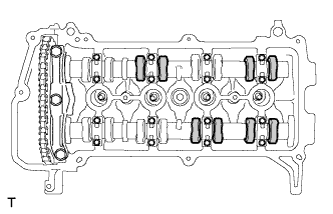
Examine the front marks and the numbers of camshaft No. 1 bearing cap and No. 2 camshaft bearing cap and check that the sequence is as shown in the illustration. Then uniformly tighten the bolts in several steps, in the sequence shown in the illustration.
Text in Illustration *a No. 1 Bearing Cap *b No. 2 Bearing Cap - Torque:
- No. 2 bearing cap:
- 13 N*m{ 129 kgf*cm , 9.4 ft.*lbf }
- No. 1 bearing cap:
- 23 N*m{ 235 kgf*cm , 17 ft.*lbf }
- NOTICE:
- Tighten each bolt uniformly while keeping the camshaft level.
 |
Using a union nut wrench 14 mm, hold the hexagonal lobe of camshaft No. 2 and install the flange bolt.
- Torque:
- 64 N*m{ 653 kgf*cm , 47 ft.*lbf }
- NOTICE:
- Use the formula to calculate special torque values for situations where a union nut wrench is combined with a torque wrench (Click here).
 |
Remove the bar from the timing chain tensioner.
Turn the crankshaft damper and align its timing notch with the timing mark "0" of the oil pump.
Text in Illustration *a Timing Notch
 |
Check that all the pairs of timing marks are aligned.
Text in Illustration *a Paint Marks *b Timing Marks
|
Apply adhesive to the 2 or 3 threads of the screw plug.
- Adhesive:
- Toyota Genuine Adhesive 1324, Three Bond 1324 or Equivalent
Using an 8 mm hexagon wrench, install the screw plug.
- Torque:
- 15 N*m{ 153 kgf*cm , 11 ft.*lbf }
|
Install the engine mounting insulator sub-assembly RH (Click here). (for Hatchback)
Install the fan and generator V belt (Click here).
Adjust the fan and generator V belt (Click here).
Inspect the fan and generator V belt (Click here).
| 27. INSTALL CAMSHAFT TIMING OIL CONTROL VALVE ASSEMBLY |
Apply a light coat of engine oil to a new O-ring, and install it onto the camshaft timing oil control valve.
 |
Install the camshaft timing oil control valve with the bolt.
- Torque:
- 7.5 N*m{ 76 kgf*cm , 66 in.*lbf }
- NOTICE:
- Do not twist the O-ring.
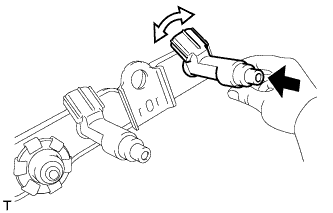
| 28. INSTALL FUEL INJECTOR ASSEMBLY |
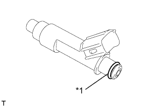 |
| *1 | O-ring |
Apply a light coat of gasoline or spindle oil to new O-rings, then install one onto each fuel injector.
Apply a light coat of gasoline or spindle oil to the contact surfaces of the fuel delivery pipe and the O-ring of the fuel injector.
While turning the fuel injector left and right, install it onto the fuel delivery pipe.
Text in Illustration 
Push 
Turn - NOTICE:
- Do not twist the O-ring.
- After installing the fuel injectors, check that they turn smoothly. If not, replace the O-ring with a new one.
- If a component has been dropped or subjected to a strong impact, replace it.
- HINT:
- Perform "Inspection After Repairs" after replacing the fuel injector assembly (Click here).
 |
| 29. INSTALL INJECTOR VIBRATION INSULATOR |
Install the 4 new injector vibration insulators onto the cylinder head.
| 30. INSTALL NO. 1 DELIVERY PIPE SPACER |
Install the 2 No. 1 delivery pipe spacers onto the cylinder head.
- NOTICE:
- Install the delivery pipe No. 1 spacer in the correct direction.
| 31. INSTALL FUEL DELIVERY PIPE SUB-ASSEMBLY |
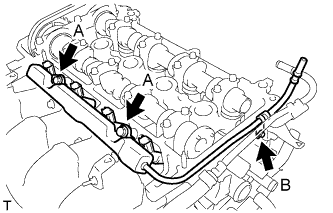 |
Install the fuel delivery pipe sub-assembly with the 4 fuel injectors, then provisionally install the 3 bolts.
- NOTICE:
- Do not drop the fuel injectors when installing the fuel delivery pipe sub-assembly.
- Check that the fuel injectors rotate smoothly after installing the fuel delivery pipe subassembly.
Tighten the 3 bolts to the specified torque.
- Torque:
- Bolt A:
- 19 N*m{ 194 kgf*cm , 14 ft.*lbf }
- Bolt B:
- 9.0 N*m{ 92 kgf*cm , 80 in.*lbf }
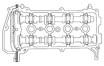
| 32. INSTALL CYLINDER HEAD COVER SUB-ASSEMBLY |
Install a new gasket onto the cylinder head cover.
Apply seal packing to the cylinder head, as shown in the illustration.
Text in Illustration 
Seal Packing - Seal Packing:
- Toyota Genuine Seal Packing Black, Three Bond 1207B or equivalent
- NOTICE:
- Remove any oil from the contact surface.
- Install the cylinder head cover sub-assembly within 3 minutes of applying seal packing.
- Do not start engine for at least 2 hours after the installation.
 |
Temporarily install the cylinder head cover sub-assembly with the 9 bolts, 2 nuts and 2 seal washers.
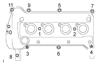 |
Tighten the 9 bolts and 2 nuts in the sequence shown in the illustration.
- Torque:
- 10 N*m{ 102 kgf*cm , 7 ft.*lbf }
| 33. INSTALL VENTILATION VALVE SUB-ASSEMBLY |
Install the ventilation valve onto the cylinder head cover.
- Torque:
- 27 N*m{ 275 kgf*cm , 20 ft.*lbf }
 |
| 34. INSTALL OIL LEVEL DIPSTICK GUIDE |
Apply engine oil to a new O-ring.
Install the O-ring onto the oil level dipstick guide.
Install the oil level dipstick guide with the bolt.
- Torque:
- 10 N*m{ 102 kgf*cm , 7 ft.*lbf }
| 35. INSTALL CRANKSHAFT POSITION SENSOR |
Apply a light coat of engine oil to the O-ring.
- NOTICE:
- If reusing the camshaft position sensor, be sure to inspect the O-ring.
Install the crankshaft position sensor with the bolt.
- Torque:
- 7.5 N*m{ 76 kgf*cm , 66 in.*lbf }
| 36. INSTALL OIL FILLER CAP GASKET |
Install the oil filler cap gasket onto the oil filler cap.
| 37. INSTALL OIL FILLER CAP SUB-ASSEMBLY |
Install the oil filler cap onto the cylinder head cover.
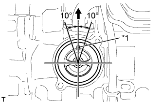
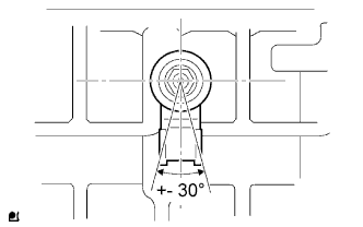
| 38. INSTALL THERMOSTAT |
Install a new gasket onto the thermostat.
Install the thermostat with the jiggle valve facing upward.
Text in Illustration *1 Jiggle Valve - HINT:
- The jiggle valve may be set within 10° of vertical in either direction, as shown in the illustration.
 |
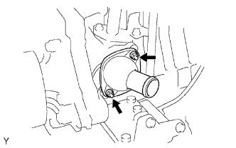
| 39. INSTALL WATER INLET |
Install the water inlet with the 2 nuts.
- Torque:
- 9.0 N*m{ 92 kgf*cm , 80 in.*lbf }
 |
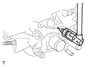
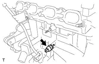
| 40. INSTALL ENGINE COOLANT TEMPERATURE SENSOR |
Install a new gasket onto the engine coolant temperature sensor.
Using a 19 mm socket wrench, install the engine coolant temperature sensor.
- Torque:
- 20 N*m{ 204 kgf*cm , 15 ft.*lbf }
- HINT:
- Perform "Inspection After Repairs" after replacing the engine coolant temperature sensor (Click here).
 |
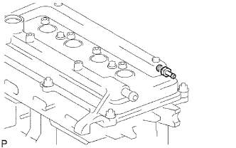
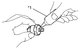
| 41. INSTALL ENGINE OIL PRESSURE SWITCH ASSEMBLY |
Apply adhesive to the end 2 or 3 threads of the engine oil pressure switch.
Text in Illustration *1 Adhesive - Adhesive:
- Toyota Genuine Adhesive 1324, Three Bond 1324 or equivalent
- NOTICE:
- Do not start the engine for at least 1 hour after the installation.
 |
Using a 24 mm deep socket wrench, install the engine oil pressure switch.
- Torque:
- 15 N*m{ 153 kgf*cm , 11 ft.*lbf }
 |
| 42. INSTALL KNOCK SENSOR |
Install the knock sensor with the nut as shown in the illustration.
- Torque:
- 20 N*m{ 204 kgf*cm , 15 ft.*lbf }
 |
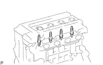
| 43. INSTALL SPARK PLUG |
Using a 16 mm spark plug wrench, install the 4 spark plugs.
- Torque:
- 18 N*m{ 184 kgf*cm , 13 ft.*lbf }
- HINT:
- Perform "Inspection After Repairs" after replacing the spark plug (Click here).
 |