CAMSHAFT (for Sedan) > REMOVAL |

- NOTICE:
- After turning the ignition switch off, waiting time may be required before disconnecting the cable from the battery terminal. Therefore, make sure to read the disconnecting the cable from the battery terminal notice before proceeding with work (Click here).
| 1. DISCONNECT CABLE FROM NEGATIVE BATTERY TERMINAL |
| 2. REMOVE ENGINE UNDER COVER RH |
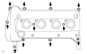
| 3. REMOVE NO. 2 CYLINDER HEAD COVER |
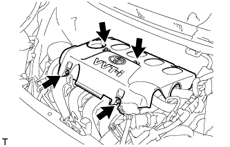 |
Remove the 4 nuts and cylinder head cover No. 2.
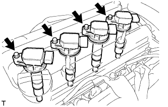
| 4. REMOVE NO. 1 IGNITION COIL |
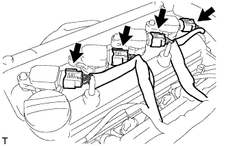 |
Disconnect the 4 ignition coil connectors.
Remove the 4 bolts and 4 ignition coils.
 |
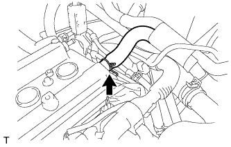
| 5. DISCONNECT VENTILATION HOSE |
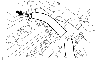 |
Disconnect the ventilation hose.
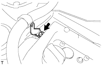
| 6. DISCONNECT FUEL VAPOR FEED HOSE ASSEMBLY |
 |
Disconnect fuel vapor feed hose assembly.
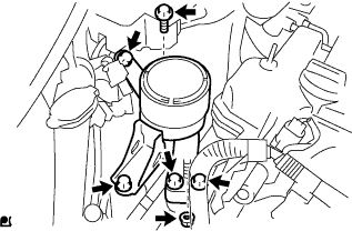
| 7. REMOVE CYLINDER HEAD COVER SUB-ASSEMBLY |
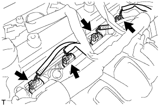 |
Disconnect the fuel injector connectors.
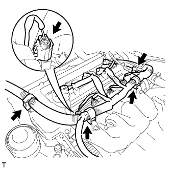
Disconnect the connector and 3 wire harness clamps shown in the illustration and disconnect the engine wire harness.
 |
Remove the bolt and remove the wire harness bracket.
 |
Remove the 9 bolts, 2 nuts and 2 seal washers and then remove the cylinder head cover sub-assembly.
 |
Remove the gasket from the cylinder head cover sub-assembly.
| 8. REMOVE FAN AND GENERATOR V BELT |
Loosen bolts A and B.
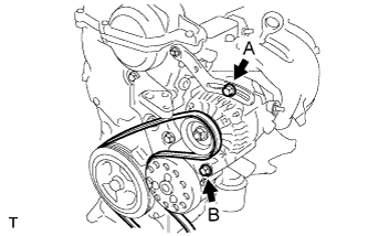 |
Release the fan and generator V belt tension and remove the fan and generator V belt.
| 9. REMOVE ENGINE MOUNTING INSULATOR SUB-ASSEMBLY RH |
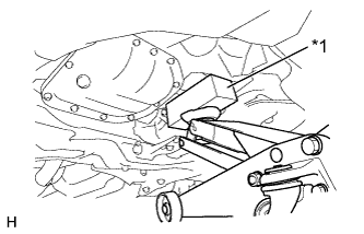 |
Place a wooden block on a jack underneath the oil pan sub-assembly.
Text in Illustration *1 Wooden Block - NOTICE:
- To prevent the No. 2 oil pan sub-assembly from deforming, do not place any attachments onto the No. 2 oil pan sub-assembly.
Remove the 5 bolts, the nut and the engine mounting insulator sub-assembly RH from the transverse engine engine mounting bracket and the vehicle.
 |
| 10. REMOVE NO. 2 CAMSHAFT |
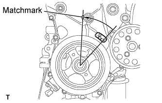 |
- NOTICE:
- When rotating the camshaft with the timing chain removed, rotate the crankshaft damper counterclockwise 40 ° from the TDC and align its timing notch with the matchmark of the timing chain cover to prevent the pistons from coming into contact with the valves.
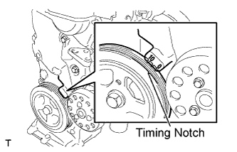
Set the No. 1 cylinder to TDC / compression.
Turn the crankshaft damper, and align its timing notch with the timing mark "0" of the oil pump.
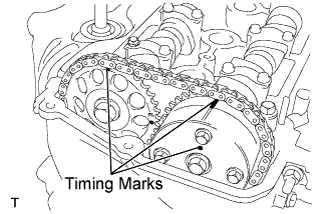
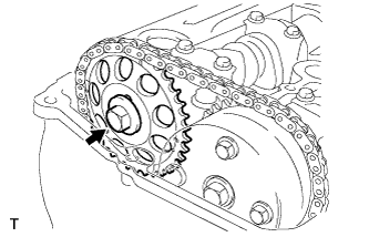
Check that the timing marks on both the camshaft timing sprocket and the camshaft timing gear are facing upward, as shown in the illustration.
- HINT:
- If not, turn the crankshaft 1 complete revolution (360°) and align the marks as above.
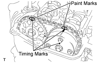
Place paint marks on the chain in the places where the timing marks of the camshaft timing sprocket and the camshaft timing gear are located.
 |
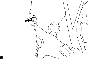
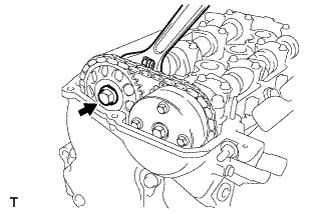
Using an 8 mm hexagon wrench, remove the screw plug.
 |
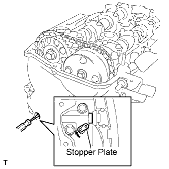
Insert a screwdriver into the service hole in the chain tensioner to pull the stopper plate of the chain tensioner upward.
 |
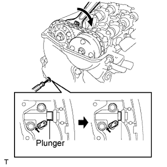
Using a wrench, rotate No. 2 camshaft clockwise to push in the plunger of the chain tensioner.
 |
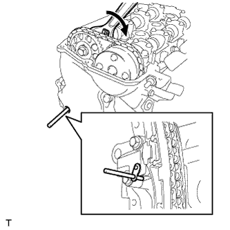
Remove the screwdriver from the service hole, then align the hole in the stopper plate with the service hole and insert a 3 mm (0.12 in.) diameter bar into the holes to hold the stopper plate.
- HINT:
- Fix the stopper plate using the bar while rotating the camshaft right and left slightly.
- Hold the bar with tape so that it does not come off.
 |
Using a wrench, hold the hexagonal lobe of No. 2 camshaft and remove the flange bolt.
 |
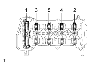
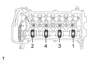
Using several steps, loosen and remove the 11 bearing cap bolts uniformly in the sequence shown in the illustration, then remove camshaft bearing caps No. 1 and No. 2.
- NOTICE:
- Loosen the bolts uniformly while keeping the camshaft level.
 |
Remove the flange bolt and remove the camshaft timing sprocket.
 |
Remove No. 2 camshaft.
 |
| 11. REMOVE CAMSHAFT |
Using several steps, loosen and remove the 8 bearing cap bolts uniformly in the sequence shown in the illustration, then remove No. 2 camshaft bearing cap.
- NOTICE:
- Loosen each bolt uniformly while keeping the camshaft level.
 |
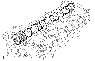
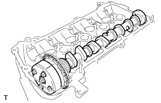
Hold the chain by hand, and remove the camshaft and the camshaft timing gear assembly.
 |
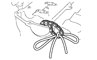
Tie the chain with a piece of string as shown in the illustration.
 |
| 12. REMOVE CAMSHAFT TIMING GEAR ASSEMBLY |
Clamp the camshaft in a vise and confirm that it is locked.
- NOTICE:
- Do not damage the camshaft.
Cover the 4 oil paths of the cam journal with tape as shown in the illustration.
- HINT:
- One of the 2 grooves located on the cam journal is for retarding cam timing (upper) and the other is for advancing cam timing (lower). Each groove has 2 oil paths. Plug one of the oil paths for each groove with a piece of rubber before wrapping the cam journal with the tape.
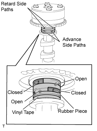 |
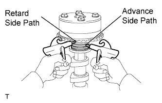
Puncture the tape covering the advance oil path and the retard oil path on the opposite side from the advance oil path.
Apply air at about 150 kPa (1.5 kgf*cm2) pressure into the 2 broken paths (the advance side path and the retard side path).
- NOTICE:
- Cover the paths with a shop rag or piece of cloth to prevent oil splashes.
 |
Confirm that the camshaft timing gear assembly revolves in the timing advance direction when the air pressure on the timing retard path is reduced.
- HINT:
- The lock pin is released, and the camshaft timing gear revolves in the advance direction.
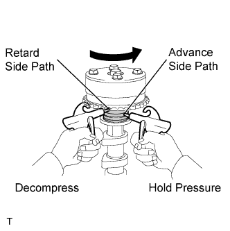 |
When the camshaft timing gear reaches the most advanced position, release the air pressure on the timing retard side path, and then release the air pressure on the timing advance side path.
- NOTICE:
- The camshaft timing gear assembly occasionally shifts to the retard side abruptly, if the air pressure on the advance side path is released first. This often results in breakage of the lock pin.
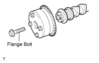
Remove the flange bolt and remove the camshaft timing gear assembly.
- NOTICE:
- Do not remove the other 4 bolts.
- When reusing the camshaft timing gear, unlock the lock pin inside the camshaft timing gear first.
 |