A/F SENSOR HEATER RELAY > ON-VEHICLE INSPECTION |

for Preparation Click here
| 1. REMOVE INTEGRATION RELAY (UNIT E) |
Remove the engine room relay block cover.
Using a screwdriver, detach the 2 claws and remove the integration relay from the engine room relay block.
- HINT:
- Tape the screwdriver tip before use.
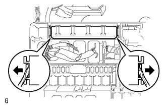 |
Disconnect the 3 connectors.
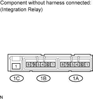
| 2. INSPECT INTEGRATION RELAY (A/F) |
- NOTICE:
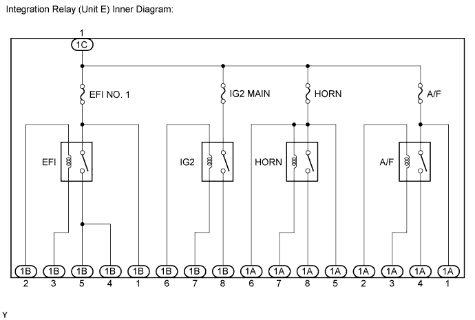
- Some relays are built into the integration relay (unit E). The integration relay cannot be disassembled. If there is a malfunction in the circuit of the integration relay, replace the integration relay.
- The internal circuit of the integration relay is as shown in the illustration below. Inspect the integration relay using the following procedures.
Measure the resistance of the A/F fuse.
Measure the resistance according to the value(s) in the table below.
- Standard Resistance:
Tester Connection Condition Specified Condition A/F fuse Always Below 1 Ω
Measure the resistance of the A/F sensor heater relay circuit.
Measure the resistance according to the value(s) in the table below.
- Standard Resistance:
Tester Connection Condition Specified Condition 1C-1 - 1A-4 When battery voltage is not applied to terminals 1A-2 and 1A-3 10 kΩ or higher When battery voltage is applied to terminals 1A-2 and 1A-3 Below 1 Ω
 |
| 3. INSTALL INTEGRATION RELAY (UNIT E) |
Connect the 3 connectors.
Install the integration relay to the engine room relay block.
Install the engine room relay block cover.