TOUCH SELECT 2-4 AND HIGH-LOW SYSTEM > ON-VEHICLE INSPECTION |

for Preparation Click here
| 1. INSPECT INDICATOR LIGHT |
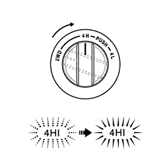
4HI Indicator Light:
Turn the ignition switch ON.
Change the 4WD control switch from 2WD to 4H.
Check the 4HI indicator light.
- OK:
Switch Condition Specified Condition 2WD to 4H 4HI indicator light comes on or 4HI indicator light comes on after it is blinking
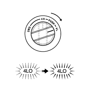
4LO Indicator Light:
Turn the ignition switch ON.
Change the 4WD control switch from 2WD to 4H. Then change it from 4H to 4L after the 4HI indicator light illuminates (after 4H switch completion).
Check the 4LO indicator light.
- OK:
Switch Condition Specified Condition After 2WD to 4WD HIGH switch completion, 4H to 4L 4LO indicator light comes on or 4LO indicator light comes on after it is blinking
| 2. INSPECT FUSE (4WD) |
Remove the 4WD fuse from the main body ECU.
Measure the resistance according to the value(s) in the table below.
- Standard resistance:
Tester Connection Condition Specified Condition 4WD fuse Always Below 1 Ω
| 3. INSPECT 4WD CONTROL ECU (POWER SUPPLY) |
Measure the voltage according to the value(s) in the table below.
- Standard voltage:
Tester Connection Switch Condition Specified Condition A26-3 (IG) - Body ground Ignition switch ON 11 to 14 V
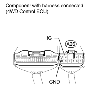 |
Measure the resistance according to the value(s) in the table below.
- Standard resistance:
Tester Connection Condition Specified Condition A26-4 (GND) - Body ground Always Below 1 Ω
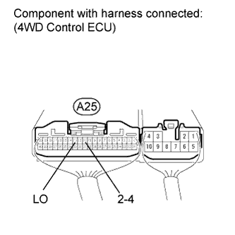
| 4. INSPECT 4WD CONTROL ECU (4WD CONTROL SWITCH) |
Measure the voltage according to the value(s) in the table below.
- Standard voltage:
Tester Connection Switch Condition Specified Condition A25-11 (2-4) - Body ground Ignition switch ON
4WD control switch 2WD positionBelow 1.5 V Ignition switch ON
4WD control switch 4H positionBelow 1.5 V Ignition switch ON
4WD control switch 4L position10.5 to 14 V A25-13 (LO) - Body ground Ignition switch ON
4WD control switch 2WD position10.5 to 14 V Ignition switch ON
4WD control switch 4H positionBelow 1.5 V Ignition switch ON
4WD control switch 4L positionBelow 1.5 V
 |
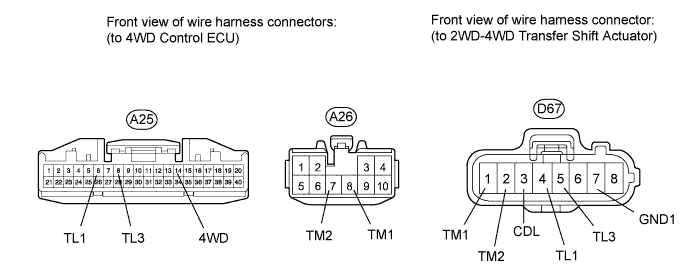
| 5. INSPECT 2WD-4WD TRANSFER SHIFT ACTUATOR |
- HINT:
- After inspecting the power supply or 4WD control switch, inspect the 2WD-4WD transfer shift actuator.
Check the harness and connector (ECU - 2WD-4WD transfer shift actuator).
Disconnect the D67 actuator connector.
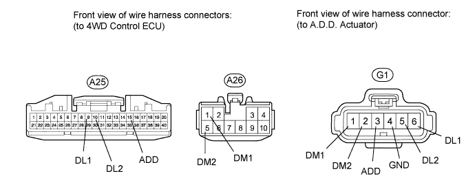
Disconnect the A25 and A26 ECU connectors.
Measure the resistance according to the value(s) in the table below.
- Standard resistance:
Tester Connection Condition Specified Condition A25-6 (TL1) - D67-4 (TL1) Always Below 1 Ω A25-6 (TL1) - Body ground Always 10 kΩ or higher A25-8 (TL3) - D67-5 (TL3) Always Below 1 Ω A25-8 (TL3) - Body ground Always 10 kΩ or higher A25-14 (4WD) - D67-3 (CDL) Always Below 1 Ω A25-14 (4WD) - Body ground Always 10 kΩ or higher A26-7 (TM2) - D67-2 (TM2) Always Below 1 Ω A26-7 (TM2) - Body ground Always 10 kΩ or higher A26-8 (TM1) - D67-1 (TM1) Always Below 1 Ω A26-8 (TM1) - Body ground Always 10 kΩ or higher D67-7 (GND1) - Body ground Always Below 1 Ω
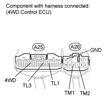
Check the 4WD control ECU (2WD-4WD transfer shift actuator).
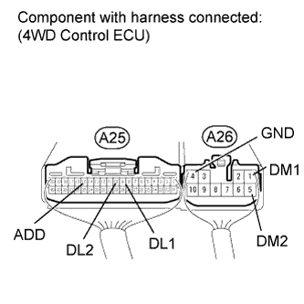
Connect the A25 and A26 ECU connectors.
Connect the D67 actuator connector.
Measure the voltage according to the value(s) in the table below.
- Standard voltage:
Tester Connection Switch Condition Specified Condition A26-8 (TM1) - A26-4 (GND) Ignition switch ON
4WD control switch 2WD → 4H position
(during transfer shift actuator 2WD to 4WD HIGH switching operation)10 to 14 V Ignition switch ON
4WD control switch 2WD → 4H position
(transfer shift actuator 2WD to 4WD HIGH switching operation stopped)Below 1.5 V A26-7 (TM2) - A26-4 (GND) Ignition switch ON
4WD control switch 4H → 2WD position
(during transfer shift actuator 4WD HIGH to 2WD switching operation)10 to 14 V Ignition switch ON
4WD control switch 4H → 2WD position
(transfer shift actuator 4WD HIGH to 2WD switching operation stopped)Below 1.5 V A25-6 (TL1) - A26-4 (GND) Ignition switch ON
4WD control switch 2WD positionBelow 1.5 V Ignition switch ON
4WD control switch 2WD → 4H position10.5 to 14 V A25-8 (TL3) - A26-4 (GND) Ignition switch ON
4WD control switch 2WD position11 to 14 V Ignition switch ON
4WD control switch 2WD → 4H positionBelow 1.5 V A25-14 (4WD) - A26-4 (GND) Ignition switch ON
4WD control switch 2WD position9.5 to 14 V Ignition switch ON
4WD control switch 2WD → 4H positionBelow 1.5 V
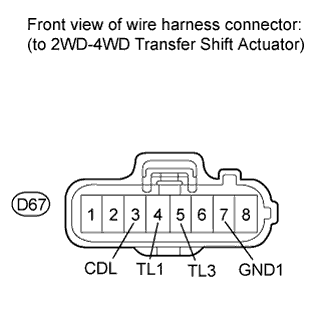
Check the 4WD control ECU.
Disconnect the D67 actuator connector.
Connect the A25 and A26 ECU connectors.
Measure the voltage according to the value(s) in the table below.
- Standard voltage:
Tester Connection Switch Condition Specified Condition D67-3 (CDL) - D67-7 (GND1) Ignition switch ON 9.5 to 14 V D67-4 (TL1) - D67-7 (GND1) Ignition switch ON 10.5 to 14 V D67-5 (TL3) - D67-7 (GND1) Ignition switch ON 10.5 to 14 V
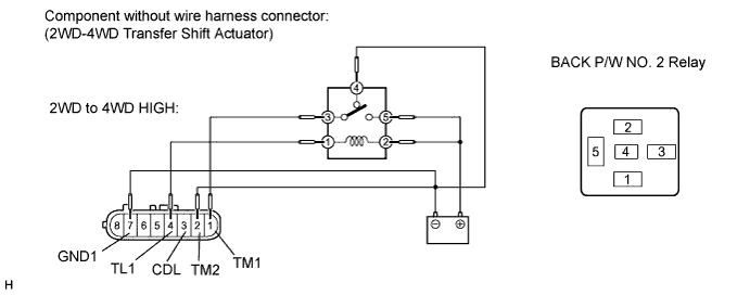
Inspect the 2WD-4WD transfer shift actuator.
Remove the transfer shift actuator (Click here).
Check the 2WD to 4WD HIGH switch.
Connect lines via a relay as shown in the illustration, then check that the actuator fork moves from the 2WD to 4WD HIGH position.- NOTICE:
- Make sure to perform this inspection with the actuator removed from the vehicle. If this inspection is performed with the actuator installed to the vehicle, the actuator will be damaged.
- When inspecting the actuator, make sure to operate it with the lines connected via a relay. If the lines are not connected via a relay and battery voltage is directly applied to the actuator, the actuator will be damaged.
- HINT:
- When inspecting the operation described above, use the BACK P/W NO. 2 relay.
- After the 2WD to 4WD HIGH switch is complete, inspect the 4WD detection switch and limit switch.
- Standard resistance:
Tester Connection Condition Specified Condition 3 (CDL) - 7 (GND1) After 2WD to 4WD HIGH switch is complete Below 1 Ω 4 (TL1) - 7 (GND1) After 2WD to 4WD HIGH switch is complete 100 kΩ or higher 5 (TL3) - 7 (GND1) After 2WD to 4WD HIGH switch is complete Below 1 Ω
Check the 4WD HIGH to 2WD switch.
Connect lines via a relay as shown in the illustration, then check that the actuator fork moves from the 4WD HIGH to 2WD position.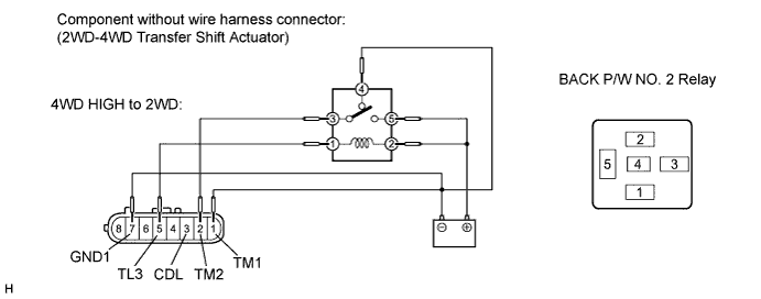
- After the 4WD HIGH to 2WD switch is complete, inspect the 4WD detection switch and limit switch.
- Standard resistance:
Tester Connection Condition Specified Condition 3 (CDL) - 7 (GND1) After 4WD HIGH to 2WD switch is complete 100 kΩ or higher 4 (TL1) - 7 (GND1) After 4WD HIGH to 2WD switch is complete Below 1 Ω 5 (TL3) - 7 (GND1) After 4WD HIGH to 2WD switch is complete 100 kΩ or higher
- After the 4WD HIGH to 2WD switch is complete, inspect the 4WD detection switch and limit switch.
| 6. INSPECT A.D.D. ACTUATOR |
- HINT:
- After inspecting the 2WD-4WD transfer shift actuator, inspect the A.D.D. actuator.
Check the harness and connector (ECU - A.D.D. actuator).
Disconnect the A25 and A26 ECU connectors.
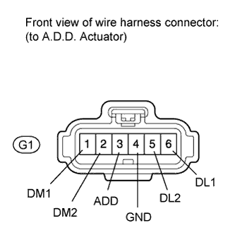
Disconnect the G1 actuator connector.
Measure the resistance according to the value(s) in the table below.
- Standard resistance:
Tester Connection Condition Specified Condition A25-9 (DL1) - G1-6 (DL1) Always Below 1 Ω A25-9 (DL1) - Body ground Always 100 kΩ or higher A25-10 (DL2) - G1-5 (DL2) Always Below 1 Ω A25-10 (DL2) - Body ground Always 100 kΩ or higher A25-15 (ADD) - G1-3 (ADD) Always Below 1 Ω A25-15 (ADD) - Body ground Always 100 kΩ or higher A26-1 (DM1) - G1-1 (DM1) Always Below 1 Ω A26-1 (DM1) - Body ground Always 100 kΩ or higher A26-5 (DM2) - G1-2 (DM2) Always Below 1 Ω A26-5 (DM2) - Body ground Always 100 kΩ or higher G1-4 (GND) - Body ground Always Below 1 Ω
Check the 4WD control ECU (A.D.D. actuator).
Connect the A25 and A26 ECU connectors.
Connect the G1 actuator connector.
Measure the voltage according to the value(s) in the table below.
- Standard voltage:
Tester Connection Switch Condition Specified Condition A26-5 (DM2) - A26-4 (GND) Ignition switch ON
4WD control switch 2WD → 4H position
(during A.D.D. actuator Free to Lock operation)10 to 14 V Ignition switch ON
4WD control switch 2WD → 4H position
(A.D.D. actuator Free to Lock operation stopped)Below 1.5 V A26-1 (DM1) - A26-4 (GND) Ignition switch ON
4WD control switch 4H → 2WD position
(during A.D.D. actuator Lock to Free operation)10 to 14 V Ignition switch ON
4WD control switch 4H → 2WD position
(A.D.D. actuator Lock to Free operation stopped)Below 1.5 V A25-9 (DL1) - A26-4 (GND) Ignition switch ON
4WD control switch 2WD position (A.D.D. actuator Free)10.5 to 14 V Ignition switch ON
4WD control switch 2WD → 4H position (A.D.D. actuator Lock)Below 1.5 V A25-10 (DL2) - A26-4 (GND) Ignition switch ON
4WD control switch 2WD position (A.D.D. actuator Free)Below 1.5 V Ignition switch ON
4WD control switch 2WD → 4H position (A.D.D. actuator Lock)10.5 to 14 V A25-15 (ADD) - A26-4 (GND) Ignition switch ON
4WD control switch 2WD position10 to 14 V Ignition switch ON
4WD control switch 2WD → 4H positionBelow 1.5 V
Check the 4WD control ECU.
Connect the A25 and A26 ECU connectors.
Disconnect the G1 actuator connector.
Measure the voltage according to the value(s) in the table below.
- Standard voltage:
Tester Connection Switch Condition Specified Condition G1-3 (ADD) - G1-4 (GND) Ignition switch ON 10 to 14 V G1-5 (DL2) - G1-4 (GND) Ignition switch ON 10.5 to 14 V G1-6 (DL1) - G1-4 (GND) Ignition switch ON 10.5 to 14 V
Inspect the A.D.D. actuator.
Remove the A.D.D. actuator (Click here).
Check the Free to Lock switch.
Connect lines via a relay as shown in the illustration, then check that the actuator fork moves from the Free to Lock position.- NOTICE:
- Make sure to perform this inspection with the actuator removed from the vehicle. If this inspection is performed with the actuator installed to the vehicle, the actuator will be damaged.
- When inspecting the actuator, make sure to operate it with the lines connected via a relay. If the lines are not connected via a relay and battery voltage is directly applied to the actuator, the actuator will be damaged.
- HINT:
- When inspecting the operation described above, use the BACK P/W NO. 2 relay.
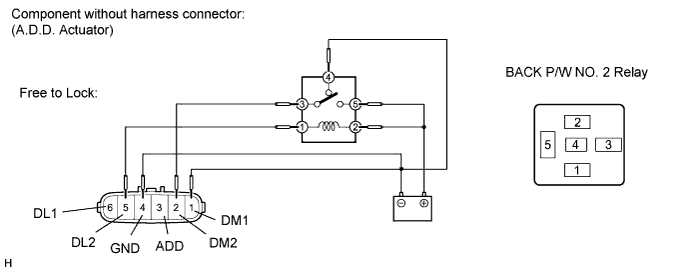
- After the Free to Lock switch is complete, inspect the A.D.D. detection switch and limit switch.
- Standard resistance:
Tester Connection Condition Specified Condition 3 (ADD) - 4 (GND) After Free to Lock switch is complete Below 1 Ω 5 (DL2) - 4 (GND) After Free to Lock switch is complete 100 kΩ or higher 6 (DL1) - 4 (GND) After Free to Lock switch is complete Below 1 Ω
Check the Lock to Free switch.
Connect lines via a relay as shown in the illustration, then check that the actuator fork moves from the Lock to Free position.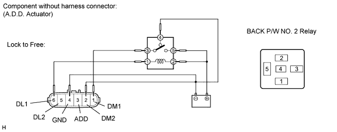
- After the Lock to Free switch is complete, inspect the A.D.D. detection switch and limit switch.
- Standard resistance:
Tester Connection Condition Specified Condition 3 (ADD) - 4 (GND) After Lock to Free switch is complete 100 kΩ or higher 5 (DL2) - 4 (GND) After Lock to Free switch is complete Below 1 Ω 6 (DL1) - 4 (GND) After Lock to Free switch is complete 100 kΩ or higher
- After the Lock to Free switch is complete, inspect the A.D.D. detection switch and limit switch.
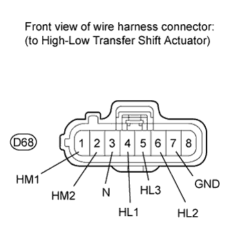
| 7. INSPECT HIGH-LOW TRANSFER SHIFT ACTUATOR |
- HINT:
- Before the inspection, check that the system is switched from 2WD to 4WD normally.
Check the harness and connector (ECU - actuator).
Disconnect the D68 high-low transfer shift actuator connector.
Disconnect the A25 and A26 ECU connector.
Measure the resistance according to the value(s) in the table below.
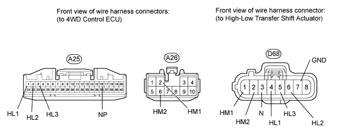
- Standard resistance:
Tester Connection Condition Specified Condition A25-1 (HL1) - D68-4 (HL1) Always Below 1 Ω A25-1 (HL1) - Body ground Always 100 kΩ or higher A25-2 (HL2) - D68-6 (HL2) Always Below 1 Ω A25-2 (HL2) - Body ground Always 100 kΩ or higher A25-3 (HL3) - D68-5 (HL3) Always Below 1 Ω A25-3 (HL3) - Body ground Always 100 kΩ or higher A25-16 (NP) - D68-3 (N) Always Below 1 Ω A25-16 (NP) - Body ground Always 100 kΩ or higher A26-2 (HM1) - D68-1 (HM1) Always Below 1 Ω A26-2 (HM1) - Body ground Always 100 kΩ or higher A26-6 (HM2) - D68-2 (HM2) Always Below 1 Ω A26-6 (HM2) - Body ground Always 100 kΩ or higher D68-7 (GND) - Body ground Always Below 1 Ω
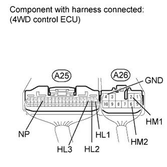
Check the 4WD control ECU (high-low transfer shift actuator).
Connect the A25 and A26 ECU connectors.
Connect the D68 actuator connector.
Measure the voltage according to the value(s) in the table below.
- Standard voltage:
Tester Connection Switch Condition Specified Condition A26-6 (HM2) - A26-4 (GND) Ignition switch ON
4WD control switch 4H → 4L position
(during transfer shift actuator 4WD HIGH to 4WD LOW operation)10 to 14 V Ignition switch ON
4WD control switch 4H → 4L position
(transfer shift actuator 4WD HIGH to 4WD LOW operation stopped)Below 1.5 V A26-2 (HM1) - A26-4 (GND) Ignition switch ON
4WD control switch 4L → 4H
(during transfer shift actuator 4WD LOW to 4WD HIGH operation)10 to 14 V Ignition switch ON
4WD control switch 4L → 4H position
(transfer shift actuator 4WD LOW to 4WD HIGH operation stopped)Below 1.5 V A25-1 (HL1) - A26-4 (GND) Ignition switch ON
4WD control switch 4H positionBelow 1.5 V Ignition switch ON
4WD control switch 4H → 4L position10.5 to 14 V A25-2 (HL2) - A26-4 (GND) Ignition switch ON
4WD control switch 4H position10.5 to 14 V Ignition switch ON
4WD control switch 4H → 4L positionBelow 1.5 V A25-3 (HL3) - A26-4 (GND) Ignition switch ON
4WD control switch 4H position10.5 to 14 V Ignition switch ON
1.5 seconds or less after 4WD control switch is changed from 4H to 4LBelow 1.5 V Ignition switch ON
Over 1.5 seconds after 4WD control switch is changed from 4H to 4L10.5 to 14 V A25-16 (NP) - A26-4 (GND) Ignition switch ON
1.5 seconds or less after 4WD control switch is changed from 4H to 4LBelow 1.5 V Ignition switch ON
Over 1.5 seconds after 4WD control switch is changed from 4H to 4L10 to 14 V
Check the 4WD control ECU.
Connect the A25 and A26 ECU connectors.
Disconnect the D68 actuator connector.
Measure the voltage according to the value(s) in the table below.
- Standard voltage:
Tester Connection Switch Condition Specified Condition D68-3 (N) - D68-7 (GND) Ignition switch ON 10 to 14 V D68-4 (HL1) - D68-7 (GND) Ignition switch ON 10.5 to 14 V D68-5 (HL3) - D68-7 (GND) Ignition switch ON 10.5 to 14 V D68-6 (HL2) - D68-7 (GND) Ignition switch ON 10.5 to 14 V
Inspect the high-low transfer shift actuator.
Remove the transfer shift actuator (Click here).
Check the 4WD HIGH to 4WD LOW switch.
Connect lines via a relay as shown in the illustration, then check that the actuator fork moves from the 4WD HIGH to 4WD LOW position.- NOTICE:
- Make sure to perform this inspection with the actuator removed from the vehicle. If this inspection is performed with the actuator installed to the vehicle, the actuator will be damaged.
- When inspecting the actuator, make sure to operate it with the lines connected via a relay. If the lines are not connected via a relay and battery voltage is directly applied to the actuator, the actuator will be damaged.
- HINT:
- When inspecting the operation described above, use the BACK P/W NO. 2 relay.
- After the 4WD HIGH to 4WD LOW switch is complete, inspect the neutral detection switch and limit switch.
- Standard resistance:
Tester Connection Condition Specified Condition 3 (N) - 7 (GND) After 4WD HIGH to 4WD LOW switch is complete 100 kΩ or higher 4 (HL1) - 7 (GND) After 4WD HIGH to 4WD LOW switch is complete 100 kΩ or higher 5 (HL3) - 7 (GND) After 4WD HIGH to 4WD LOW switch is complete 100 kΩ or higher 6 (HL2) - 7 (GND) After 4WD HIGH to 4WD LOW switch is complete Below 1 Ω
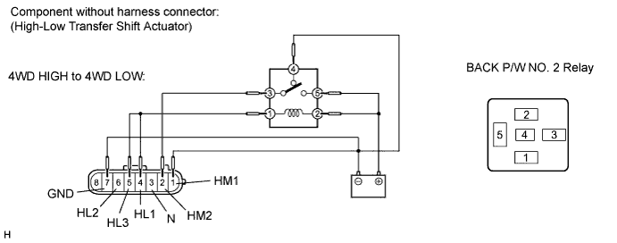
Check the 4WD LOW to 4WD HIGH switch.
Connect lines via a relay as shown in the illustration, then check that the actuator fork moves from the 4WD LOW to 4WD HIGH position.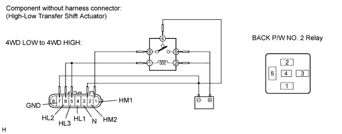
- After the 4WD LOW to 4WD HIGH switch is complete, inspect the neutral detection switch and limit switch.
- Standard resistance:
Tester Connection Condition Specified Condition 3 (N) - 7 (GND) After 4WD LOW to 4WD HIGH switch is complete 100 kΩ or higher 4 (HL1) - 7 (GND) After 4WD LOW to 4WD HIGH switch is complete Below 1 Ω 5 (HL3) - 7 (GND) After 4WD LOW to 4WD HIGH switch is complete 100 kΩ or higher 6 (HL2) - 7 (GND) After 4WD LOW to 4WD HIGH switch is complete 100 kΩ or higher
- After the 4WD LOW to 4WD HIGH switch is complete, inspect the neutral detection switch and limit switch.