DTC P050A Cold Start Idle Air Control System Performance |

for Preparation Click here
DESCRIPTION
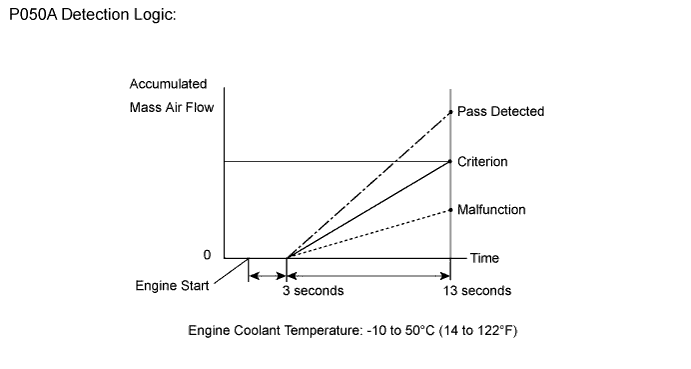
This monitor will run when the engine is started with the engine coolant temperature at -10 to 50°C (14 to 122°F). The DTC will be set after the engine idles for 13 seconds (2 trip detection logic).The DTC is designed to monitor the idle air control at cold start. When the engine is started with the engine coolant temperature at lower than 50°C (122°F), the ECM (PCM) measures the accumulated mass air flow at engine idling. If it does not reach the criteria within 10 seconds, the ECM (PCM) interprets this as a malfunction. The MIL is illuminated and a DTC is set when the malfunction is detected in consecutive driving cycles (2 trip detection logic).
The ETCS (Electronic Throttle Control System) controls the idle speed. The ETCS operates the throttle actuator to open and close the throttle valve, and adjusts the intake air amount to achieve the target idle speed.
- NOTICE:
- When the negative battery terminal is disconnected during inspections or repairs, the ISC (Idle Speed Control) learning values are cleared. This DTC cannot be set with the ISC learning values cleared.
- The ISC learning is performed when the engine is warmed up and has been idling for 5 minutes.
| DTC Code | DTC Detection Condition | Trouble Area |
| P050A | Insufficient mass air flow at cold start (2 trip detection logic) |
|
MONITOR STRATEGY
| Related DTCs | P050A: Cold start idle air speed control system |
| Required sensors/Components (Main) | Throttle body |
| Required sensors/Components (Related) | Mass air flow meter Engine coolant temperature sensor |
| Frequency of operation | Once per driving cycle |
| Duration | 10 seconds |
| MIL operation | 2 driving cycles |
| Sequence of operation | None |
TYPICAL ENABLING CONDITIONS
| Monitor runs whenever following DTCs not present | P0010, P0020 (VVT Oil control valve) P0011, P0021 (VVT System - Advance) P0012, P0022 (VVT System - Retard) P0013, P0023 (Exhaust VVT Oil control valve) P0014, P0024 (Exhaust VVT System - Advance) P0015, P0025 (Exhaust VVT System - Retard) P0016, P0018 (VVT System - Misalignment) P0017, P0019 (Exhaust VVT System - Misalignment) P0102, P0103 (Mass air flow meter) P0115, P0117, P0118 (Engine coolant temperature sensor) P0120, P0121, P0122, P0123, P0220, P0222, P0223, P2135 (Throttle position sensor) P0125 (Insufficient coolant temperature for closed loop fuel control) P0171, P0172, P0174, P0175 (Fuel system) P0301 - P0308 (Misfire) P0335 (Crankshaft position sensor) P0340, P0342, P0343, P0345, P0347, P0348 (VVT sensor) P0351 - P0358 (Igniter) P0365, P0367, P0368, P0390, P0392, P0393 (Exhaust VVT sensor) P0500 (Vehicle speed sensor) P0705 (Shift lever position switch) P014C, P014D, P014E, P014F, P015A, P015B, P015C, P015D, P2195, P2196, P2197, P2198, P2237, P2238, P2239, P2240, P2241, P2242, P2252, P2253, P2255, P2256 (Air fuel ratio sensor) P1340 (Camshaft position sensor) |
| Battery voltage | 8 V or more |
| Time after engine start | 3 seconds or more |
| Starter | OFF |
| ECT at engine start | -10°C (14°F) or more |
| ECT | -10 to 50°C (14 to 122°F) |
| Engine idling | 3 seconds or more |
| Fuel-cut | OFF |
| Vehicle speed | Less than 3 km/h (1.875 mph) |
| Time after shift position changed | 2 seconds or more |
| Atmospheric pressure | 76 kPa (570 mmHg) or more |
TYPICAL MALFUNCTION THRESHOLDS
| Accumulated mass air flow | Less than 116 g (varies with ECT) |
CONFIRMATION DRIVING PATTERN
- Connect the Techstream to the DLC3.
- Turn the ignition switch to ON and turn the Techstream on.
- Clear DTCs (even if no DTCs are stored, perform the clear DTC operation).
- Turn the ignition switch off and wait for at least 30 seconds.
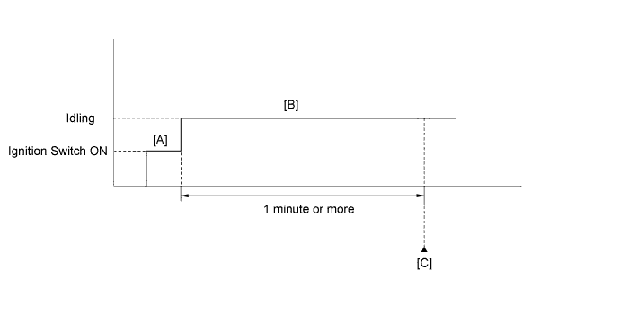
- Turn the ignition switch to ON and turn the Techstream on [A].
- Enter the following menu items: Powertrain / Engine and ECT / Data List / All Data / Coolant Temp.
- Check that "Coolant Temp" in the Data List is within the range of -10 to 50°C (14 to 122°F).
- Start the engine and warm it up until the coolant temperature is the same as the coolant temperature in the freeze frame data.
- Idle the engine for 1 minute or more [B].
- Enter the following menus: Powertrain / Engine and ECT / Trouble Codes [C].
- Read the Pending DTCs.
- HINT:
- If a pending DTC is output, the system is malfunctioning.
- If a pending DTC is not output, perform the following procedure.
- Enter the following menus: Powertrain / Engine and ECT / Utility / All Readiness.
- Input the DTC: P050A.
- Check the DTC judgment result.
Tester Display Description NORMAL - DTC judgment completed
- System normal
ABNORMAL - DTC judgment completed
- System abnormal
INCOMPLETE - DTC judgment not completed
- Perform driving pattern after confirming DTC enabling conditions
N/A - Unable to perform DTC judgment
- Number of DTCs which do not fulfill DTC preconditions has reached ECU's memory limit
- HINT:
- If the judgment result shows ABNORMAL, the system has a malfunction.
- If the judgment result shows INCOMPLETE or N/A, idle the engine for 3 minutes, let the engine cool down, and then perform steps [A] through [C].
- DTC judgment completed
- If the test result is INCOMPLETE or N/A and no pending DTC is output, perform a universal trip and check for permanent DTCs (Click here).
- HINT:
- If a permanent DTC is output, the system is malfunctioning.
- If no permanent DTC is output, the system is normal.
INSPECTION PROCEDURE
| 1.CHECK ANY OTHER DTCS OUTPUT |
Connect the Techstream to the DLC3.
Turn the ignition switch to ON.
Turn the Techstream on.
Enter the following menus: Powertrain / Engine and ECT / Trouble Codes.
Read DTCs.
Result Result Proceed to DTC P050A A DTC P050A and other DTCs B - HINT:
- If any DTCs other than P050A are output, troubleshoot those DTCs first.
|
| ||||
| OK | |
| 2.READ VALUE USING TECHSTREAM (FUEL TRIM) |
- HINT:
- Calculate the total fuel trim values to check the characteristic deviation of the mass air flow meter.
Connect the Techstream to the DLC3.
Turn the ignition switch to ON and turn the Techstream on.
Start the engine.
Enter the following menus: Powertrain / Engine and ECT / Data List / A/F Control System / Short FT #1 and Long FT #1, or Short FT #2 and Long FT #2.
Read the values displayed on the Techstream.
Add together the Short FT #1 and Long FT #1, or Short FT #2 and Long FT #2 values to obtain the total fuel trim.
- Result:
- Total of Short FT #1 and Long FT #1, or Short FT #2 and Long FT #2 values is between -20% and 20%.
|
| ||||
| OK | |
| 3.INSPECT THROTTLE BODY |
Check for deposits around the throttle valve and throttle valve condition.
- OK:
- No deposits around throttle valve and throttle valve moves smoothly.
|
| ||||
|
| ||||
| 4.REPAIR OR REPLACE THROTTLE BODY ASSEMBLY |
|
| ||||
| 5.CHECK PCV SYSTEM |
Check the PCV hose connections (Click here).
- OK:
- PCV hose is connected correctly and is not damaged.
|
| ||||
| OK | |
| 6.CHECK AIR INDUCTION SYSTEM |
Check the air induction system for vacuum leakage (Click here).
|
| ||||
| OK | |
| 7.CHECK AIR CLEANER FILTER |
Visually check that the air cleaner filter is not excessively contaminated with dirt or oil.
- OK:
- The air cleaner filter element is not excessively contaminated with dirt or oil.
|
| ||||
| OK | |
| 8.PERFORM ACTIVE TEST USING TECHSTREAM (OPERATE OCV) |
Connect the Techstream to the DLC3.
Start the engine.
Turn the Techstream on
Warm up the engine.
Enter the following menus: Powertrain / Engine and ECT / Active Test / Control the VVT Linear (Bank 1) or Control the VVT Linear (Bank 2).
Check the engine speed while operating the Oil Control Valve (OCV) using the Techstream.
- OK:
Operation Specified Condition 0% Normal engine speed 100% Engine idles roughly or stalls
- HINT:
- Refer to "Data List / Active Test" [VVT OCV Duty #1, VVT Change Angle #1, VVT OCV Duty #2 and VVT Change Angle #2] (Click here).
|
| ||||
| OK | |
| 9.READ VALUE USING TECHSTREAM (MAF) |
Connect the Techstream to the DLC3.
Turn the ignition switch to ON.
Turn the Techstream on.
Enter the following menus: Powertrain / Engine and ECT / Data List / All Data / MAF and Coolant Temp.
Allow the engine to idle until the Coolant Temp reaches 75°C (167°F) or more.
Read MAF with the engine speed at 3000 rpm.
- Standard:
- Between 18.0 gm/s and 27.0 gm/s (shift lever: N; A/C: Off).
|
| ||||
|
| ||||
| 10.REPAIR OR REPLACE PCV SYSTEM |
Repair or replace the PCV system.
|
| ||||
| 11.REPAIR OR REPLACE AIR INDUCTION SYSTEM |
Repair or replace the air induction system.
|
| ||||
| 12.REPLACE AIR CLEANER FILTER |
Replace the air cleaner filter element sub-assembly.
|
| ||||
| 13.CHECK AND REPAIR VVT SYSTEM |
Check and repair the VVT system.
- HINT:
- Refer to DTC P0011 Inspection Procedure (Click here).
| NEXT | |
| 14.CHECK WHETHER DTC OUTPUT RECURS (DTC P050A) |
- NOTICE:
- For this operation, the engine must be cold (the same level as the engine coolant temperature recorded in the freeze frame data).
Connect the Techstream to the DLC3.
Turn the ignition switch to ON.
Turn the Techstream on.
Clear DTCs (Click here).
Turn the ignition switch off and wait for at least 30 seconds.
Turn the ignition switch to ON and turn the Techstream on.
Enter the following menus: Powertrain / Engine and ECT / Data List / All Data / Coolant Temp.
Check that the engine coolant temperature is between - 10°C and 50°C (14 and 122°F).
Start the engine and warm it up.
Drive the vehicle in accordance with the driving pattern described in Confirmation Driving Pattern.
Enter the following menus: Powertrain / Engine and ECT / Utility / All Readiness.
Input the DTC: P050A.
Check the DTC judgment result.
Result Result Proceed to NORMAL (DTC is not output) A ABNORMAL (DTC P050A is output) B
|
| ||||
| A | ||
| ||
| 15.CHECK HARNESS AND CONNECTOR (MASS AIR FLOW METER CONNECTOR CONNECTION) |
Check the connection and terminal contact pressure of connectors and wire harnesses between the mass air flow meter and ECM (Click here).
- HINT:
- Repair any problems.
| NEXT | |
| 16.CHECK WHETHER DTC OUTPUT RECURS (DTC P050A) |
- NOTICE:
- For this operation, the engine must be cold (the same level as the engine coolant temperature recorded in the freeze frame data).
Connect the Techstream to the DLC3.
Turn the ignition switch to ON.
Turn the Techstream on.
Clear DTCs (Click here).
Turn the ignition switch off and wait for at least 30 seconds.
Turn the ignition switch to ON and turn the Techstream on.
Enter the following menus: Powertrain / Engine and ECT / Data List / All Data / Coolant Temp.
Check that the engine coolant temperature is between - 10°C and 50°C (14 and 122°F).
Start the engine and warm it up.
Drive the vehicle in accordance with the driving pattern described in Confirmation Driving Pattern.
Enter the following menus: Powertrain / Engine and ECT / Utility / All Readiness.
Input the DTC: P050A.
Check the DTC judgment result.
Result Result Proceed to ABNORMAL (DTC P050A is output) A NORMAL (DTC is not output) B
|
| ||||
| A | |
| 17.CHECK HARNESS AND CONNECTOR (MASS AIR FLOW METER - ECM) |
Disconnect the D7 MAF meter connector.
Disconnect the D74 ECM connector.
Measure the resistance according to the value(s) in the table below.
- Standard resistance:
Tester Connection Condition Specified Condition D7-3 (VG) - D74-74 (VG) Always Below 1 Ω D7-2 (E2G) - D74-75 (E2G) Always Below 1 Ω D7-3 (VG) or D74-74 (VG) - Body ground Always 10 kΩ or higher
|
| ||||
| OK | |
| 18.REPLACE MASS AIR FLOW METER |
Replace the mass air flow meter (Click here).
- HINT:
- If the result of the inspection performed in step 9 indicated no problem, proceed to the next step without replacing the mass air flow meter.
| NEXT | |
| 19.CHECK WHETHER DTC OUTPUT RECURS (DTC P050A) |
- NOTICE:
- For this operation, the engine must be cold (the same level as the engine coolant temperature recorded in the freeze frame data).
Connect the Techstream to the DLC3.
Turn the ignition switch to ON.
Turn the Techstream on.
Clear DTCs (Click here).
Turn the ignition switch off and wait for at least 30 seconds.
Turn the ignition switch to ON and turn the Techstream on.
Enter the following menus: Powertrain / Engine and ECT / Data List / All Data / Coolant Temp.
Check that the engine coolant temperature is between - 10°C and 50°C (14 and 122°F).
Start the engine and warm it up.
Drive the vehicle in accordance with the driving pattern described in Confirmation Driving Pattern.
Enter the following menus: Powertrain / Engine and ECT / Utility / All Readiness.
Input the DTC: P050A.
Check the DTC judgment result.
Result Result Proceed to NORMAL (DTC is not output) A ABNORMAL (DTC P050A is output) B
|
| ||||
| A | ||
| ||