DTC C1310/11 Open or Short in Active Brake Booster Circuit |

for Preparation Click here
DESCRIPTION
Operates when booster's negative pressure is insufficient and allows for a stable braking control.| DTC Code | DTC Detection Condition | Trouble Area |
| C1310/11 | Open or short in active brake booster solenoid circuit. |
|
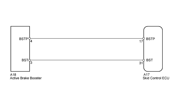
WIRING DIAGRAM
INSPECTION PROCEDURE
- NOTICE:
- When replacing the VSC actuator assembly, perform the zero point calibration (Click here).
- HINT:
- When the brake warning light illuminates, inspect and repair the trouble areas of the brake booster vacuum line first.
| 1.CHECK BRAKE BOOSTER ASSEMBLY |
Disconnect the A18 booster connector.
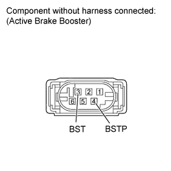 |
Measure the resistance according to the value(s) in the table below.
- Standard Resistance:
Tester Connection Condition Specified Condition 3 (BST) - 4 (BSTP) Always 1.1 to 1.7 Ω
|
| ||||
| OK | |
| 2.CHECK HARNESS AND CONNECTOR (SKID CONTROL ECU - ACTIVE BRAKE BOOSTER) |
Confirm that the skid control ECU connector and active brake booster connector are properly connected.
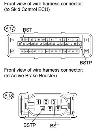 |
Disconnect the A17 ECU connector.
Disconnect the A18 booster connector.
Inspect both the connector case and the terminal for deformation and corrosion.
- OK:
- No deformation or corrosion.
Measure the resistance according to the value(s) in the table below.
- Standard Resistance:
Tester Connection Condition Specified Condition A17-31 (BST) - A18-3 (BST) Always Below 1 Ω A17-31 (BST) - Body ground Always 10 kΩ or higher A17-17 (BSTP) - A18-4 (BSTP) Always Below 1 Ω A17-17 (BSTP) - Body ground Always 10 kΩ or higher
|
| ||||
| OK | ||
| ||