FRONT SPEED SENSOR > INSTALLATION |

for Preparation Click here
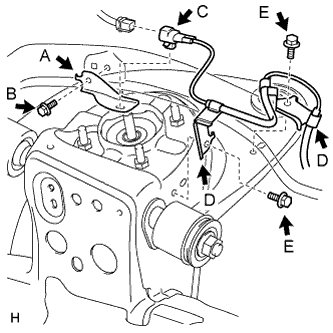
| 1. INSTALL FRONT SKID CONTROL SENSOR CLAMP LH |
Install the skid control sensor clamp (labeled A) with the bolt (labeled B).
- Torque:
- 13 N*m{ 127 kgf*cm , 9 ft.*lbf }
- NOTICE:
- Install the bracket so that the rotation stopper (labeled C) touches the knuckle.
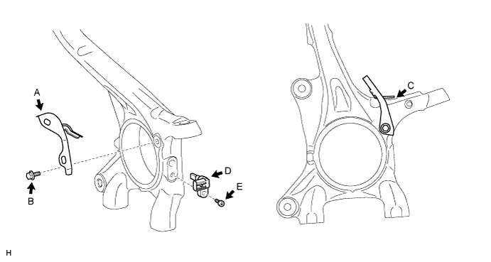
| 2. INSTALL FRONT SPEED SENSOR LH |
Install the speed sensor (labeled D) with the hexagon socket head cap bolt (labeled E).
- Torque:
- 11 N*m{ 107 kgf*cm , 8 ft.*lbf }
- NOTICE:
- Make sure there are no pieces of iron or other foreign matter attached to the sensor tip part.
- While inserting the speed sensor into the knuckle hole, do not strike or damage the sensor tip part.
- After installing the speed sensor, make sure there is no clearance or foreign matter between the sensor stay part and the knuckle.
- Make sure there is no foreign matter attached to the magnetic rotor.
| 3. INSTALL FRONT SKID CONTROL SENSOR WIRE LH |
Connect the connector (labeled A).
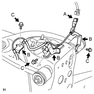 |
Install the 3 harness clamps (labeled B) with the 3 bolts (labeled C).
- Torque:
- 13 N*m{ 127 kgf*cm , 9 ft.*lbf }
- NOTICE:
- When installing the clamps, do not twist the wire harness.
- For clamps with rotation stoppers, make sure the rotation stopper touches the installation position.
Install the harness clamp with the bolt (labeled D).
- Torque:
- 13 N*m{ 127 kgf*cm , 9 ft.*lbf }
- NOTICE:
- When installing the clamp, do not twist the wire harness.
- Make sure the clamp's rotation stopper touches the installation position.
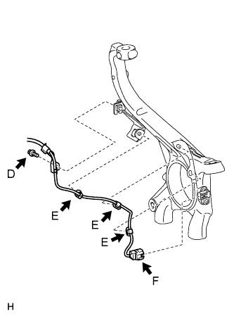 |
Attach the 3 clips (labeled E).
- NOTICE:
- When installing the clips, do not twist the wire harness.
- When installing the clips, securely insert them as shown in the illustration.
Connect the speed sensor connector (labeled F).
- NOTICE:
- Securely connect the connector.
| 4. INSTALL FRONT SKID CONTROL SENSOR CLAMP RH |
Install the skid control sensor clamp (labeled A) with the bolt (labeled B).
- Torque:
- 13 N*m{ 127 kgf*cm , 9 ft.*lbf }
- NOTICE:
- Install the bracket so that the rotation stopper (labeled C) touches the knuckle.
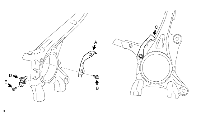
| 5. INSTALL FRONT SPEED SENSOR RH |
Install the speed sensor (labeled D) with the hexagon socket head cap bolt (labeled E).
- Torque:
- 11 N*m{ 107 kgf*cm , 8 ft.*lbf }
- NOTICE:
- Make sure there are no pieces of iron or other foreign matter attached to the sensor tip part.
- While inserting the speed sensor into the knuckle hole, do not strike or damage the sensor tip part.
- After installing the speed sensor, make sure there is no clearance or foreign matter between the sensor stay part and the knuckle.
- Make sure there is no foreign matter attached to the magnetic rotor.
| 6. INSTALL FRONT SKID CONTROL SENSOR WIRE RH |
Install the skid control sensor clamp (labeled A) with the bolt (labeled B).
- Torque:
- for Bolt B:
- 5.0 N*m{ 51 kgf*cm , 44 in.*lbf }
 |
Install the connector (labeled C) with connect the connector (labeled C).
Install the 2 harness clamps (labeled D) with the 2 bolts (labeled E).
- Torque:
- for Bolt E:
- 13 N*m{ 127 kgf*cm , 9 ft.*lbf }
- NOTICE:
- When installing the clamps, do not twist the wire harness.
- For clamps with rotation stoppers, make sure the rotation stopper touches the installation position.
Install the harness clamp with the bolt (labeled E).
- Torque:
- 13 N*m{ 127 kgf*cm , 9 ft.*lbf }
- NOTICE:
- When installing the clamp, do not twist the wire harness.
- Make sure the clamp's rotation stopper touches the installation position.
 |
Attach the 3 clips (labeled F).
- NOTICE:
- When installing the clips, do not twist the wire harness.
- When installing the clips, securely insert them as shown in the illustration.
Connect the speed sensor connector (labeled G).
- NOTICE:
- Securely connect the connector.
| 7. INSTALL FRONT WHEEL |
- Torque:
- for Aluminum Wheel:
- 131 N*m{ 1336 kgf*cm , 97 ft.*lbf }
- for Steel Wheel:
- 209 N*m{ 2131 kgf*cm , 154 ft.*lbf }
| 8. CONNECT CABLE TO NEGATIVE BATTERY TERMINAL |
| 9. CHECK SPEED SENSOR SIGNAL |
Check the speed sensor signal (Click here).