DTC P2237 Oxygen (A/F) Sensor Pumping Current Circuit / Open (Bank 1 Sensor 1) |
DTC P2238 Oxygen (A/F) Sensor Pumping Current Circuit Low (Bank 1 Sensor 1) |
DTC P2239 Oxygen (A/F) Sensor Pumping Current Circuit High (Bank 1 Sensor 1) |
DTC P2240 Oxygen (A/F) Sensor Pumping Current Circuit / Open (Bank 2 Sensor 1) |
DTC P2241 Oxygen (A/F) Sensor Pumping Current Circuit Low (Bank 2 Sensor 1) |
DTC P2242 Oxygen (A/F) Sensor Pumping Current Circuit High (Bank 2 Sensor 1) |
DTC P2252 Oxygen (A/F) Sensor Reference Ground Circuit Low (Bank 1 Sensor 1) |
DTC P2253 Oxygen (A/F) Sensor Reference Ground Circuit High (Bank 1 Sensor 1) |
DTC P2255 Oxygen (A/F) Sensor Reference Ground Circuit Low (Bank 2 Sensor 1) |
DTC P2256 Oxygen (A/F) Sensor Reference Ground Circuit High (Bank 2 Sensor 1) |

for Preparation Click here
DESCRIPTION
Refer to DTC P2195 (Click here).| DTC No. | DTC Detection Condition | Trouble Area |
| P2237 P2240 | Open in the circuit between terminals A1A+/A2A+ and A1A-/A2A- of the A/F sensor while engine is running (2 trip detection logic) |
|
| P2238 P2241 |
(2 trip detection logic): (a) A1A+/A2A+ voltage 0.5 V or less (b) (A1A+/A2A+) - (A1A-/A2A-) = 0.1 V or less
(2 trip detection logic) |
|
| P2239 P2242 | A1A+/A2A+ voltage more than 4.5 V for 5.0 seconds or more (2 trip detection logic) |
|
| P2252 P2255 | A1A-/A2A- voltage 0.5 V or less for 5.0 seconds or more (2 trip detection logic) |
|
| P2253 P2256 | A1A-/A2A- voltage more than 4.5 V for 5.0 seconds or more (2 trip detection logic) |
|
- HINT:
- DTCs P2237, P2238, P2239, P2252 and P2253 indicate malfunctions related to the bank 1 A/F sensor circuit.
- DTCs P2240, P2241, P2242, P2255 and P2256 indicate malfunctions related to the bank 2 A/F sensor circuit.
- Bank 1 refers to the bank that includes the No. 1 cylinder.
- Bank 2 refers to the bank that includes the No. 2 cylinder.
MONITOR DESCRIPTION
These DTCs are output when there is an open or short in the A/F sensor circuit, or if A/F sensor output drops.To detect these problems, the voltage of the A/F sensor is monitored when turning the ignition switch to ON, and the admittance (admittance is an electrical term that indicates the ease of flow of current) is checked while driving. If the voltage of the A/F sensor is between 0.6 V and 4.5 V, it is considered normal. If the voltage is outside of the specified range, or the admittance is less than the standard value, the ECM will determine that there is a malfunction in the A/F sensor. If the same malfunction is detected in the next driving cycle, the MIL is illuminated and a DTC is stored.
The Air-Fuel Ratio (A/F) sensor varies its output voltage in proportion to the air-fuel ratio. If the A/F sensor impedance (alternating current resistance) or output voltage deviates greatly from the standard range, the ECM determines that there is an open or short in the A/F sensor circuit.
MONITOR STRATEGY
| Related DTCs | P2237: A/F sensor (for Bank 1) open circuit between A1A+/A2A+ and A1A-/A2A- P2238: A/F sensor (for Bank 1) short circuit between A1A+/A2A+ and A1A-/A2A- P2238: A/F sensor (for Bank 1) short circuit between A1A+/A2A+ and GND P2238: A/F sensor (for Bank 1) low impedance P2239: A/F sensor (for Bank 1) short circuit between A1A+/A2A+ and +B P2240: A/F sensor (for Bank 2) open circuit between A1A+/A2A+ and A1A-/A2A- P2241: A/F sensor (for Bank 2) short circuit between A1A+/A2A+ and A1A-/A2A- P2241: A/F sensor (for Bank 2) short circuit between A1A+/A2A+ and GND P2241: A/F sensor (for Bank 1) low impedance P2242: A/F sensor (for Bank 2) short circuit between A1A+/A2A+ and +B P2252: A/F sensor (for Bank 1) short circuit between A1A-/A2A- and GND P2253: A/F sensor (for Bank 1) short circuit between A1A-/A2A- and +B P2255: A/F sensor (for Bank 2) short circuit between A1A-/A2A- and GND P2256: A/F sensor (for Bank 2) short circuit between A1A-/A2A- and +B |
| Required Sensors/Components (Main) | A/F sensor |
| Required Sensors/Components (Related) | Engine Coolant Temperature (ECT) sensor, Crankshaft position sensor |
| Frequency of Operation | Continuous |
| Duration | 10 seconds: A/F sensor open circuit between A1A+/A2A+ and A1A-/A2A- and Low impedance 5 seconds: Other |
| MIL Operation | 2 driving cycles |
| Sequence of Operation | None |
TYPICAL ENABLING CONDITIONS
| Monitor runs whenever following DTCs not present | P0016, P0018 (VVT system - Misalignment) P0017, P0019 (Exhaust VVT system - Misalignment) P0031, P0032, P0051, P0052, P101D, P103D (Air fuel ratio sensor heater) P006A, P0107, P0108 (Manifold absolute pressure) P0102, P0103 (Mass air flow meter) P0112, P0113 (Intake air temperature sensor) P0115, P0117, P0118 (Engine coolant temperature sensor) P0120, P0121, P0122, P0123, P0220, P0222, P0223, P2135 (Throttle position sensor) P0125 (Insufficient coolant temperature for closed loop fuel control) P0128 (Thermostat) P0171, P0172, P0174, P0175 (Fuel system) P0301 - P0308 (Misfire) P0335 (Crankshaft position sensor) P0401 (EGR system) P0412, P0415, P0418, P0419, P1613, P1614 (Secondary air injection system control) P0451, P0452, P0453 (EVAP system) P0500, P0722 (Vehicle speed sensor) P0505 (IAC valve) P1340 (Camshaft position sensor) P2440 - P2447 (Secondary air injection system) |
| Monitor runs whenever following DTCs not present | None |
| Battery voltage | 11 V or more |
| Engine | Running |
| Estimated sensor temperature | 450 to 550°C (842 to 1022°F) for P2237 and P2240 |
| Ignition switch | ON |
| Time after Ignition switch is OFF to ON | 5 seconds or more |
| Engine coolant temperature | 0°C (32°F) or higher |
| Estimated sensor temperature | 700 to 800°C (1292 to 1472°F) for P2238 and P2241 |
| Fuel cut | Not executed |
| Battery voltage | 11 V or higher |
| Ignition switch | ON |
| Timing after ignition switch off to ON | 5 seconds or more |
TYPICAL MALFUNCTION THRESHOLDS
| A/F sensor admittance | Less than 0.002 1/Ω |
| A/F sensor admittance | Less than 0.0074 1/Ω |
| A1A+/A2A+ terminal voltage | 0.5 V or less |
| A1A+/A2A+ terminal voltage | More than 4.5 V |
| A1A-/A2A- terminal voltage | 0.5 V or less |
| A1A-/A2A- terminal voltage | More than 4.5 V |
| Difference between A1A+ and A1A-/A2A+ and A2A- terminal voltage | 0.1 V or less |
CONFIRMATION DRIVING PATTERN
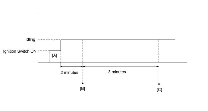
- Connect the Techstream to the DLC3.
- Turn the ignition switch to ON and turn the Techstream on.
- Clear DTCs (even if no DTCs are stored, perform the clear DTC operation).
- Turn the ignition switch off and wait for at least 30 seconds.
- Turn the ignition switch to ON and turn the Techstream on [A].
- Start the engine and wait 2 minutes.
- Enter the following menus: Powertrain / Engine and ECT / Trouble Codes [B].
- Read the pending DTCs.
- HINT:
- If a pending DTC is output, the system is malfunctioning.
- If a pending DTC is not output, perform the following procedure.
- Enter the following menus: Powertrain / Engine and ECT / Utility / All Readiness.
- Input the DTC: P2237, P2238, P2239, P2240, P2241, P2242, P2252, P2253, P2255 or P2256.
- Check the DTC judgment result.
Tester Display Description NORMAL - DTC judgment completed
- System normal
ABNORMAL - DTC judgment completed
- System abnormal
INCOMPLETE - DTC judgment not completed
- Perform driving pattern after confirming DTC enabling conditions
N/A - Unable to perform DTC judgment
- Number of DTCs which do not fulfill DTC preconditions has reached ECU memory limit
- HINT:
- If the judgment result shows ABNORMAL, the system has a malfunction.
- If the judgment result shows INCOMPLETE or N/A, idle the engine for 3 minutes and check the DTC judgment result again [C].
- DTC judgment completed
- If no pending DTC is output, perform a universal trip and check for permanent DTCs (Click here).
- HINT:
- If a permanent DTC is output, the system is malfunctioning.
- If no permanent DTC is output, the system is normal.
WIRING DIAGRAM
Refer to DTC P2195 (Click here).INSPECTION PROCEDURE
- HINT:
- Read freeze frame data using the Techstream. Freeze frame data records the engine condition when malfunctions are detected. When troubleshooting, freeze frame data can help determine if the vehicle was moving or stationary, if the engine was warmed up or not, if the air-fuel ratio was lean or rich, and other data from the time the malfunction occurred.
- Bank 1 refers to the bank that includes the No. 1 cylinder*.
*: The No. 1 cylinder is the cylinder which is farthest from the transmission. - Bank 2 refers to the bank that does not include the No. 1 cylinder.
- Sensor 1 refers to the sensor closest to the engine assembly.
- Sensor 2 refers to the sensor farthest away from the engine assembly.
| 1.CHECK HARNESS AND CONNECTOR (A/F SENSOR - ECM) |
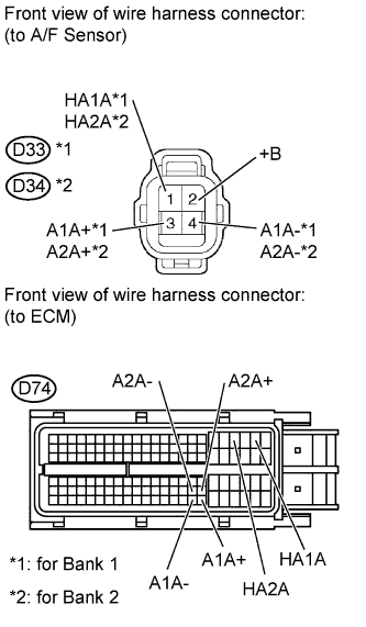 |
Disconnect the A/F sensor connector.
Disconnect the ECM connector.
Measure the resistance according to the value(s) in the table below.
- Standard Resistance:
Tester Connection Condition Specified Condition D33-1 (HA1A) - D74-22 (HA1A) Always Below 1 Ω D33-3 (A1A+) - D74-126 (A1A+) Always Below 1 Ω D33-4 (A1A-) - D74-125 (A1A-) Always Below 1 Ω D34-1 (HA2A) - D74-20 (HA2A) Always Below 1 Ω D34-3 (A2A+) - D74-103 (A2A+) Always Below 1 Ω D34-4 (A2A-) - D74-102 (A2A-) Always Below 1 Ω D33-1 (HA1A) or D74-22 (HA1A) - Body ground Always 10 kΩ or higher D33-3 (A1A+) or D74-126 (A1A+) - Body ground Always 10 kΩ or higher D33-4 (A1A-) or D74-125 (A1A-) - Body ground Always 10 kΩ or higher D34-1 (HA2A) or D74-20 (HA2A) - Body ground Always 10 kΩ or higher D34-3 (A2A+) or D74-103 (A2A+) - Body ground Always 10 kΩ or higher D34-4 (A2A-) or D74-102 (A2A-) - Body ground Always 10 kΩ or higher
|
| ||||
| OK | |
| 2.REPLACE AIR FUEL RATIO SENSOR |
Replace the air fuel ratio sensor (Click here).
| NEXT | |
| 3.CHECK WHETHER DTC OUTPUT RECURS |
Connect the Techstream to the DLC3.
Turn the ignition switch to ON.
Turn the Techstream on.
Clear DTCs (Click here).
Start the engine.
Allow the engine to idle for 5 minutes or more.
Enter the following menus: Powertrain / Engine and ECT / Trouble Codes / Pending.
Read the pending DTCs.
Result Result Proceed to No DTC is output A P2237, P2238, P2239, P2240, P2241, P2242, P2252, P2253, P2255 or P2256 is output B
|
| ||||
| A | ||
| ||