DTC P0013 Camshaft Position "B" Actuator Circuit / Open (Bank 1) |
DTC P0023 Camshaft Position "B" Actuator Circuit / Open (Bank 2) |

for Preparation Click here
DESCRIPTION
- This DTC is designed to detect opens or shorts in the camshaft oil control valve (OCV) circuit. If the OCV's duty-cycle is excessively high or low while the engine is running, the ECM will illuminate the MIL and store the DTC.
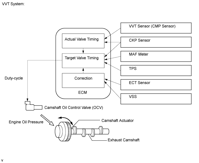
- The VVT (variable valve timing) system adjusts the intake and exhaust valve timing to improve driveability. The engine oil pressure turns the camshaft actuator to adjust the valve timing. The OCV is a solenoid valve and switches the engine oil line. The valve moves when the ECM applies 12 volts to the solenoid. The ECM changes the energizing time to the solenoid (duty-cycle) in accordance with the camshaft position, crankshaft position, throttle position, etc.
| DTC No. | DTC Detection Condition | Trouble Area |
| P0013 | Open or short in OCV for exhaust camshaft (for Bank 1) circuit (1 trip detection logic) |
|
| P0023 | Open or short in OCV for exhaust camshaft (for Bank 2) circuit (1 trip detection logic) |
|
MONITOR DESCRIPTION
This DTC is designed to detect opens or shorts in the camshaft oil control valve (OCV) circuit. If the OCV's duty-cycle is excessively high or low while the engine is running, the ECM will illuminate the MIL and store the DTC.MONITOR STRATEGY
| Related DTCs | P0013: Exhaust camshaft OCV (for Bank 1) P0023: Exhaust camshaft OCV (for Bank 2) |
| Required sensors/Components (Main) | Exhaust camshaft OCV |
| Required sensors/Components (Related) | - |
| Frequency of operation | Continuous |
| Duration | 1 second |
| MIL operation | Immediate |
| Sequence of operation | None |
TYPICAL ENABLING CONDITIONS
| Monitor runs whenever following DTCs not present | None |
| All of following conditions met | - |
| Starter | OFF |
| Ignition switch | ON |
| Time after ignition switch off to ON | 0.5 seconds or more |
| One of following conditions met | - |
| A. All of following conditions met | - |
| Battery voltage | 11 to 13 V |
| Target duty ratio | Less than 70% |
| B. All of following conditions met | - |
| Battery voltage | 13 V or more |
| Target duty ratio | Less than 80% |
| Current cut status | Not cut |
TYPICAL MALFUNCTION THRESHOLDS
| Output duty cycle | 100% or more |
| Output duty cycle | 3% or less |
COMPONENT OPERATING RANGE
| OCV duty-cycle | 3 to 100% |
CONFIRMATION DRIVING PATTERN
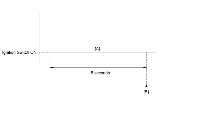
- Connect the Techstream to the DLC3.
- Turn the ignition switch to ON and turn the Techstream on.
- Clear the DTCs (even if no DTCs are stored, perform the clear DTC operation).
- Turn the ignition switch off and wait for at least 30 seconds.
- Turn the ignition switch to ON and turn the Techstream on.
- Wait 5 seconds [A].
- Enter the following menus: Powertrain / Engine and ECT / Trouble Code [B].
- Read the pending DTCs.
- HINT:
- If a pending DTC is output, the system is malfunctioning.
- If a pending DTC is not output, perform the following procedure.
- Enter the following menus: Powertrain / Engine and ECT / Utility / All Readiness.
- Input the DTC: P0013 or P0023.
- Check the DTC judgment result.
Tester Display Description NORMAL - DTC judgment completed
- System normal
ABNORMAL - DTC judgment completed
- System abnormal
INCOMPLETE - DTC judgment not completed
- Perform driving pattern after confirming DTC enabling conditions
N/A - Unable to perform DTC judgment
- Number of DTCs which do not fulfill DTC preconditions has reached ECU memory limit
- DTC judgment completed
- If the test result is INCOMPLETE or N/A and no pending DTC is output, perform a universal trip and check for permanent DTCs (Click here).
- HINT:
- If a permanent DTC is output, the system is malfunctioning.
- If no permanent DTC is output, the system is normal.
WIRING DIAGRAM
INSPECTION PROCEDURE
- HINT:
- If DTC P0013 is displayed, check the bank 1 VVT system for exhaust camshaft circuit.
- Bank 1 refers to the bank that includes the No. 1 cylinder*.
*: The No. 1 cylinder is the cylinder which is farthest from the transmission. - If DTC P0023 is displayed, check the bank 2 VVT system for exhaust camshaft circuit.
- Bank 2 refers to the bank that does not include the No. 1 cylinder.
- Read freeze frame data using the Techstream. Freeze frame data records the engine condition when malfunctions are detected. When troubleshooting, freeze frame data can help determine if the vehicle was moving or stationary, if the engine was warmed up or not, if the air-fuel ratio was lean or rich, and other data from the time the malfunction occurred.
| 1.CHECK FOR DTC (DTC P0013 OR P0023) |
Connect the Techstream to the DLC3.
Clear DTCs after recording the freeze frame data and DTC.
Turn the ignition switch off.
Allow the engine to idle and check for DTCs.
Check that P0013 or P0023 is not present.
- OK:
- P0013 or P0023 is not present.
|
| ||||
| OK | ||
| ||
| 2.INSPECT CAMSHAFT OIL CONTROL VALVE ASSEMBLY |
Disconnect the OCV connector.
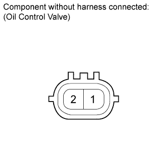 |
Remove the OCV (Click here).
Measure the resistance according to the value(s) in the table below.
- Standard Resistance:
Tester Connection Condition Specified Condition 1 - 2 20°C (68°F) 6.9 to 7.9 Ω
|
| ||||
| OK | |
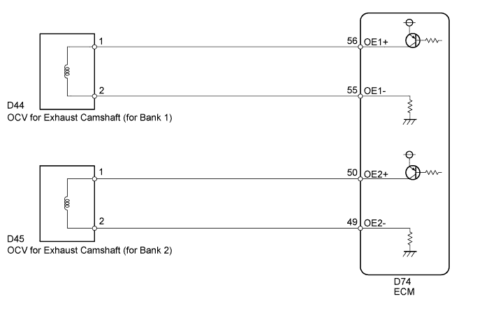
| 3.CHECK HARNESS AND CONNECTOR (OCV - ECM) |
Disconnect the OCV connector.
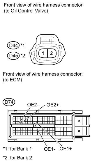 |
Disconnect the ECM connector.
Measure the resistance according to the value(s) in the table below.
- Standard Resistance:
Tester Connection Condition Specified Condition D44-1 - D74-56 (OE1+) Always Below 1 Ω D44-2 - D74-55 (OE1-) Always Below 1 Ω D45-1 - D74-50 (OE2+) Always Below 1 Ω D45-2 - D74-49 (OE2-) Always Below 1 Ω D44-1 or D74-56 (OE1+) - Body ground Always 10 kΩ or higher D44-2 or D74-55 (OE1-) - Body ground Always 10 kΩ or higher D45-1 or D74-50 (OE2+) - Body ground Always 10 kΩ or higher D45-2 or D74-49 (OE2-) - Body ground Always 10 kΩ or higher
|
| ||||
| OK | ||
| ||