DTC P0420 Catalyst System Efficiency Below Threshold (Bank 1) |
DTC P0430 Catalyst System Efficiency Below Threshold (Bank 2) |

for Preparation Click here
MONITOR DESCRIPTION
The ECM uses sensors mounted in front of and behind the Three-Way Catalytic Converter (TWC) to monitor its efficiency.The first sensor, the Air-Fuel Ratio (A/F) sensor, sends pre-catalyst information to the ECM. The second sensor, the Heated Oxygen (HO2) sensor, sends post-catalyst information to the ECM.
In order to detect any deterioration in the TWC, the ECM calculates the Oxygen Storage Capacity (OSC) of the TWC. This calculation is based on the voltage output of the HO2 sensor while performing active air-fuel ratio control.
The OSC value is an indication of the oxygen storage capacity of the TWC. When the vehicle is being driven with a warm engine, active air-fuel ratio control is performed for approximately 15 to 20 seconds. When it is performed, the ECM deliberately sets the air-fuel ratio to lean or rich levels. If the rich-lean cycle of the HO2 sensor is long, the OSC becomes greater. There is a direct correlation between the OSCs of the HO2 sensor and the TWC.
The ECM uses the OSC value to determine the state of the TWC. If any deterioration has occurred, it illuminates the MIL and sets the DTC.
| DTC Code | DTC Detection Condition | Trouble Area |
| P0420 | OSC value smaller than standard value under active air-fuel ratio control (2 trip detection logic) |
|
| P0430 | OSC value smaller than standard value under active air-fuel ratio control (2 trip detection logic) |
|
CATALYST LOCATION
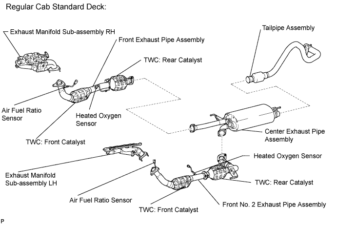
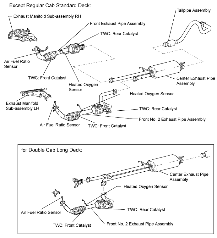
- NOTICE:
- When DTC P0420 is output, replace the front No. 2 exhaust pipe assembly when catalyst replacement is necessary. (Excluding air fuel ratio sensor and heated oxygen sensor)
- When DTC P0430 is output, replace the front exhaust pipe assembly when catalyst replacement is necessary. (Excluding air fuel ratio sensor and heated oxygen sensor)
MONITOR STRATEGY
| Related DTCs | P0420: Catalyst Deterioration (for Bank 1) P0430: Catalyst Deterioration (for Bank 2) |
| Required Sensors/Components (Main) | A/F sensor and HO2 sensor |
| Required Sensors/Components (Related) | Intake air temperature sensor, mass air flow meter, crankshaft position sensor and engine coolant temperature sensor |
| Frequency of Operation | Once per driving cycle |
| Duration | About 30 seconds |
| MIL Operation | 2 driving cycles |
| Sequence of Operation | None |
TYPICAL ENABLING CONDITIONS
| Monitor runs whenever following DTCs not present | P0010, P0020 (VVT Oil control valve) P0011, P0021 (VVT System - Advance) P0012, P0022 (VVT System - Retard) P0013, P0023 (Exhaust VVT Oil control valve) P0014, P0024 (Exhaust VVT System - Advance) P0015, P0025 (Exhaust VVT System - Retard) P0016, P0018 (VVT System - Misalignment) P0017, P0019 (Exhaust VVT System - Misalignment) P0031, P0032, P0051, P0052, P101D, P103D (Air fuel ratio sensor heater) P0037, P0038, P0057, P0058, P102D, P105D (Rear oxygen sensor heater) P0102, P0103 (Mass air flow meter) P0115, P0117, P0118 (Engine coolant temperature sensor) P0120, P0121, P0122, P0123, P0220, P0222, P0223, P2135 (Throttle position sensor) P0125 (Insufficient coolant temperature for closed loop fuel control) P0136, P0137, P0138, P0139, P0156, P0157, P0158, P0159, P0607 (Rear oxygen sensor) P0171, P0172, P0174, P0175 (Fuel system) P0301 - P0308 (Misfire) P0335 (Crankshaft position sensor) P1340 (Camshaft position sensor) P0340, P0342, P0343, P0345, P0347, P0348 (VVT sensor) P0351 - P0358 (Igniter) P0365, P0367, P0368, P0390, P0392, P0393 (Exhaust VVT sensor) P0412, P0415, P0418, P0419, P1613, P1614 (Secondary air injection system control) P2440 - P2447 (Secondary air injection system) P0500 (Vehicle speed sensor) P014C, P014D, P014E, P014F, P015A, P015B, P015C, P015D, P2195, P2196, P2197, P2198, P2237, P2238, P2239, P2240, P2241, P2242, P2252, P2253, P2255, P2256 (Air fuel ratio sensor) |
| Battery voltage | 11 V or more |
| Intake air temperature | -10°C (14°F) or more |
| Engine coolant temperature | 75°C (167°F) or more |
| Atmospheric pressure | 76 kPa (570 mmHg) or more |
| Idling | OFF |
| Engine speed | Less than 3200 rpm |
| A/F sensor status | Activated |
| Fuel system status | Closed loop |
| Engine load | 10 to 75% |
| All of following conditions (a), (b) and (c) met | - |
| (a) Mass air flow rate | 7.5 to 75 g/s |
| (b) Estimated front catalyst temperature | 575 to 820°C (1067 to 1508°F) |
| (c) Estimated rear catalyst temperature | 400 to 700°C (752 to 1292°F) |
| Shift position | 4th or higher |
TYPICAL MALFUNCTION THRESHOLDS
| Oxygen Storage Capacity (OSC) of Three-Way Catalytic Converter (TWC) | Less than 0.12 g |
MONITOR RESULT
Refer to CHECKING MONITOR STATUS (Click here).CONFIRMATION DRIVING PATTERN
- HINT:
- Performing this confirmation driving pattern will activate the catalyst efficiency monitor. This is very useful for verifying the completion of a repair.
- Connect the Techstream to the DLC3.
- Turn the ignition switch to ON.
- Turn the Techstream on.
- Clear DTCs (even if no DTCs are stored, perform the clear DTC operation).
- Turn the ignition switch off and wait for at least 30 seconds.
- Turn the ignition switch to ON and turn the Techstream on.
- Enter the following menus: Powertrain / Engine and ECT / Monitor / Current Monitor.
- Check that Catalyst Efficiency / Current is Incomplete.
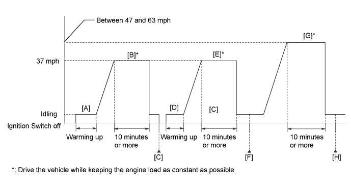
- Start the engine and warm it up until the engine coolant temperature is 75°C (167°F) or higher [A].
- Drive the vehicle at approximately 60 km/h (37 mph) for 10 minutes or more [B].
- CAUTION:
- When performing the confirmation driving pattern, obey all speed limits and traffic laws.
- HINT:
- Drive the vehicle while keeping the engine load as constant as possible.
- Turn the ignition switch off and wait for at least 30 seconds [C].
- Turn the ignition switch to ON and turn the Techstream on.
- Start the engine and warm it up until the engine coolant temperature is 75°C (167°F) or higher [D].
- Drive the vehicle at approximately 60 km/h (37 mph) for 10 minutes or more [E].
- CAUTION:
- When performing the confirmation driving pattern, obey all speed limits and traffic laws.
- HINT:
- Drive the vehicle while keeping the engine load as constant as possible.
- The monitor item will change to Complete as the Catalyst Efficiency monitor operates [F].
- Enter the following menus: Powertrain / Engine and ECT / Trouble Codes.
- Check if any DTCs (pending DTCs) are stored.
- HINT:
- If the monitor item does not change to Complete, and no pending DTCs are stored, perform the following procedure.
- Drive the vehicle at a speed between 75 and 100 km/h (47 and 63 mph) for 10 minutes or more [G].
- CAUTION:
- When performing the confirmation driving pattern, obey all speed limits and traffic laws.
- HINT:
- Drive the vehicle while keeping the engine load as constant as possible.
- The monitor item will change to Complete as the Catalyst Efficiency monitor operates [H].
- Enter the following menus: Powertrain / Engine and ECT / Trouble Codes.
- Check if any DTCs (pending DTCs) are stored.
- HINT:
- If the monitor item does not change to Complete, and no pending DTCs are stored, extend the driving time.
- If no pending DTC is output, perform a universal trip and check for permanent DTCs (Click here).
- HINT:
- If a permanent DTC is output, the system is malfunctioning.
- If no permanent DTC is output, the system is normal.
CONDITIONING FOR SENSOR TESTING
- HINT:
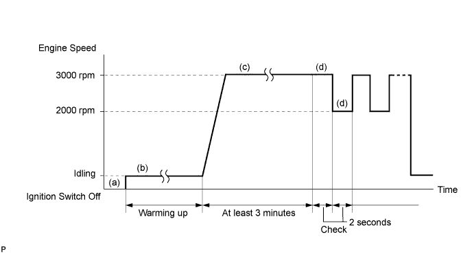
- Perform the operation with the engine speeds and time durations described below prior to checking the waveforms of the A/F and HO2 sensors. This is in order to activate the sensors sufficiently to obtain the appropriate inspection results.
- (a) Connect the Techstream to the DLC3.
- (b) Start the engine and warm it up with all the accessories switched OFF until the engine coolant temperature stabilizes.
- (c) Run the engine at an engine speed of between 2500 rpm and 3000 rpm for at least 3 minutes.
- (d) While running the engine at 3000 rpm and 2000 rpm at 2 second intervals, check the waveforms of the A/F and HO2 sensors using the Techstream.
- HINT:
- If either voltage output of the Air-Fuel Ratio (A/F) or Heated Oxygen (HO2) sensor does not fluctuate, or there is a noise in the waveform of either sensor, the sensor may be malfunctioning.
- If the voltage outputs of both the sensors remain lean or rich, the air-fuel ratio may be extremely lean or rich. In such cases, perform the following Control the Injection Volume for A/F Sensor using the Techstream.
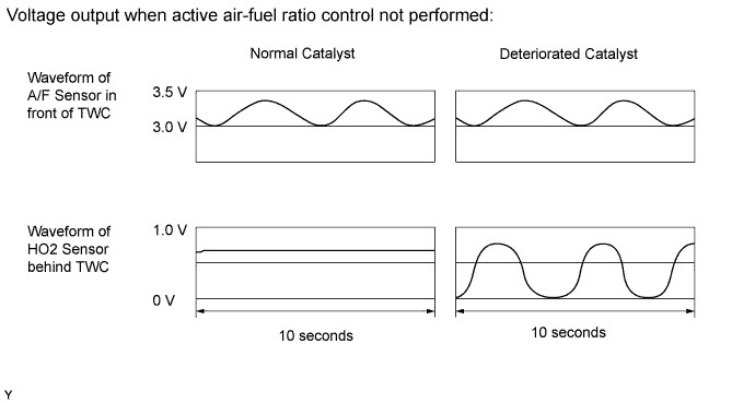
- If the Three-Way Catalytic Converter (TWC) has deteriorated, the HO2 sensor (located behind the TWC) voltage output fluctuates up and down frequently, even under normal driving conditions (active air-fuel ratio control is not performed).
INSPECTION PROCEDURE
- HINT:
- Malfunctioning areas can be identified by performing the Control the Injection Volume for A/F sensor function provided in the Active Test. The Control the Injection Volume for A/F sensor function can help to determine whether the Air-Fuel Ratio (A/F) sensor, Heated Oxygen (HO2) sensor and other potential trouble areas are malfunctioning.
- The following instructions describe how to conduct the Control the Injection Volume for A/F sensor operation using the Techstream.
- Connect the Techstream to the DLC3.
- Start the engine and turn the Techstream on.
- Warm up the engine at an engine speed of 2500 rpm for approximately 90 seconds.
- On the Techstream, enter the following menus: Powertrain / Engine / Active Test / Control the Injection Volume for A/F sensor.
- Perform the Active Test operation with the engine idling (press the RIGHT or LEFT button to change the fuel injection volume.)
- Monitor the output voltages of the A/F and HO2 sensors (AFS Voltage B1S1 and O2S B1S2 or AFS Voltage B2S1 and O2S B2S2) displayed on the Techstream.
- HINT:
- Change the fuel injection volume within the range of -12.5% to +12.5%
- The air fuel ratio sensor has an output delay of a few seconds and the heated oxygen sensor has a maximum output delay of approximately 20 seconds.
- If the sensor output voltage does not change (almost no reaction) while performing the Active Test, the sensor may be malfunctioning.
| Tester Display (Sensor) | Injection Volume | Status | Voltage |
| AFS Voltage B1S1 or AFS Voltage B2S1 (A/F) | +12.5% | Rich | Less than 3.1 V |
| AFS Voltage B1S1 or AFS Voltage B2S1 (A/F) | -12.5% | Lean | More than 3.4 V |
| O2S B1S2 or O2S B2S2 (HO2) | +12.5% | Rich | More than 0.55 V |
| O2S B1S2 or O2S B2S2 (HO2) | -12.5% | Lean | Less than 0.4 V |
- NOTICE:
- The Air-Fuel Ratio (A/F) sensor has an output delay of a few seconds and the Heated Oxygen (HO2) sensor has a maximum output delay of approximately 20 seconds.
| Case | A/F Sensor (Sensor 1) Output Voltage | HO2 Sensor (Sensor 2) Output Voltage | Main Suspected Trouble Area |
| 1 | 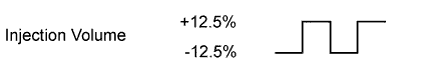 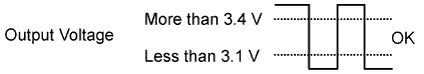 | 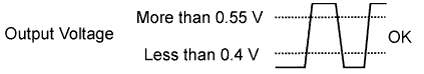 | - |
| 2 |  | |
|
| 3 | | |
|
| 4 | | |
|
- Following the Control the Injection Volume for A/F sensor procedure enables technicians to check and graph the voltage outputs of both the A/F and HO2 sensors.
- To display the graph, enter the following menus: Powertrain / Engine / Active Test / Control the Injection Volume for A/F Sensor / A/F Control System / AFS Voltage B1S1 and O2S B1S2 or AFS Voltage B2S1 and O2S B2S2.
- HINT:
- If a malfunction cannot be found when troubleshooting DTC P0420 or P0430, a lean or rich abnormality may be the cause. Perform troubleshooting by following the inspection procedure for P0171 or P0174 (System Too Lean) and P0172 or P0175 (System Too Rich).
- Read freeze frame data using the Techstream. Freeze frame data records the engine condition when malfunctions are detected. When troubleshooting, freeze frame data can help determine if the vehicle was moving or stationary, if the engine was warmed up or not, if the air-fuel ratio was lean or rich, and other data from the time the malfunction occurred.
| 1.CHECK ANY OTHER DTCS OUTPUT (IN ADDITION TO DTC P0420 OR P0430) |
Connect the Techstream to the DLC3.
Turn the ignition switch to ON.
Turn the Techstream on.
Enter the following menus: Powertrain / Engine and ECT / Trouble Codes.
Read DTCs.
Result Result Proceed to DTC P0420 or P0430 is output A DTC P0420 or P0430 and other DTCs are output B - HINT:
- If any DTCs other than P0420 or P0430 are output, troubleshoot those DTCs first.
|
| ||||
| A | |
| 2.PERFORM ACTIVE TEST USING TECHSTREAM (CONTROL THE INJECTION VOLUME) |
Connect the Techstream to the DLC3.
Start the engine.
Turn the Techstream on.
Warm up the engine and run the engine at an engine speed of 2500 rpm for approximately 90 seconds.
Enter the following menus: Powertrain / Engine and ECT / Active Test / Control the Injection Volume for A/F Sensor.
Perform the Control the Injection Volume for A/F Sensor operation with the engine idling.
Monitor the voltage outputs of the air fuel ratio and heated oxygen sensors (AFS Voltage B1S1 and O2S B1S2 or AFS Voltage B2S1 and O2S B2S2) displayed on the Techstream.
- HINT:
- Change the fuel injection volume within the range of -12.5% to +12.5%.
- The air fuel ratio sensor has an output delay of a few seconds and the heated oxygen sensor has a maximum output delay of approximately 20 seconds.
- If the sensor output voltage does not change (almost no reaction) while performing the Active Test, the sensor may be malfunctioning.
Techstream Display (Sensor) Injection Volume Status Voltage AFS Voltage B1S1 or AFS Voltage B2S1
(Air fuel ratio)+12.5% Rich Below 3.1 V -12.5% Lean Higher than 3.4 V O2S B1S2 or O2S B2S2
(Heated oxygen)+12.5% Rich Higher than 0.55 V -12.5% Lean Below 0.4 V
Lean: During the Control the Injection Volume Active Test, the air fuel ratio sensor output voltage (AFS Voltage) is consistently higher than 3.4 V, and the heated oxygen sensor output voltage (O2S) is consistently below 0.4 V.Result Status of AFS Voltage B1S1 or AFS Voltage B2S1 Status of O2S B1S2 or O2S B2S2 Air Fuel Ratio Condition and Air Fuel Ratio and Heated Oxygen Sensor Condition Suspected Trouble Area Proceed to Lean/Rich Lean/Rich Normal - Three-way catalytic converter
- Gas leaks from exhaust system
A Lean Lean/Rich Air fuel ratio sensor malfunction Air fuel ratio sensor B Rich Lean/Rich Air fuel ratio sensor malfunction Air fuel ratio sensor B Lean/Rich Lean Heated oxygen sensor malfunction - Heated oxygen sensor
- Gas leaks from exhaust system
C Lean/Rich Rich Heated oxygen sensor malfunction - Heated oxygen sensor
- Gas leaks from exhaust system
C Lean Lean Actual air fuel ratio lean - Extremely rich or lean actual air fuel ratio
- Gas leaks from exhaust system
D Rich Rich Actual air fuel ratio rich - Extremely rich or lean actual air fuel ratio
- Gas leaks from exhaust system
D
Rich: During the Control the Injection Volume Active Test, the AFS Voltage is consistently below 3.1 V, and the O2S is consistently higher than 0.55 V.
Lean/Rich: During the Control the Injection Volume Active Test, the output voltage of the air fuel ratio sensor and heated oxygen sensor alternate correctly.
Refer to "Data List / Active Test" [AFS Voltage B1S1, AFS Voltage B2S1, O2S B1S2 and O2S B2S2] (Click here).
|
| ||||
|
| ||||
|
| ||||
| A | |
| 3.CHECK FOR EXHAUST GAS LEAK |
Check for exhaust gas leaks from the exhaust manifold sub-assembly and exhaust pipes.
- OK:
- No gas leaks.
|
| ||||
| OK | |
| 4.CHECK DTC OUTPUT (DTC P0420 AND/OR P0430) |
- NOTICE:
- When DTC P0420 is output, replace the front No. 2 exhaust pipe assembly (TWC: Front catalyst and rear catalyst) when catalyst replacement is necessary.
- When DTC P0430 is output, replace the front exhaust pipe assembly (TWC: Front catalyst and rear catalyst) when catalyst replacement is necessary.
- HINT:
- Confirm the replacement parts, referring to the illustration in the Catalyst Location.
Connect the Techstream to the DLC3.
Turn the ignition switch to ON.
Turn the Techstream ON.
Enter the following menus: Powertrain / Engine and ECT / Trouble Codes.
Read the DTCs.
Result Result Proceed to DTC P0420 is output (for Regular Cab Standard Deck) A DTC P0430 is output (for Regular Cab Standard Deck) B DTC P0420 is output (except Regular Cab Standard Deck) C DTC P0430 is output (except Regular Cab Standard Deck) D DTC P0420 and P0430 are output (for Regular Cab Standard Deck) A and B DTC P0420 and P0430 are output (except Regular Cab Standard Deck) C and D
|
| ||||
|
| ||||
|
| ||||
| D | ||
| ||
| 5.CHECK FOR EXHAUST GAS LEAK |
Check for exhaust gas leaks from the exhaust manifold assembly and exhaust pipes.
- OK:
- No gas leaks.
|
| ||||
|
| ||||
| 6.CHECK FOR EXHAUST GAS LEAK |
Check for exhaust gas leaks from the exhaust manifold assembly and exhaust pipes.
- OK:
- No gas leaks.
|
| ||||
|
| ||||
| 7.REPLACE AIR FUEL RATIO SENSOR |
Replace the air fuel ratio sensor (Click here).
|
| ||||
| 8.REPAIR OR REPLACE FOR EXHAUST GAS LEAK POINT |
Repair or replace exhaust gas leak point.
|
| ||||
| 9.REPLACE HEATED OXYGEN SENSOR |
Replace the heated oxygen sensor (Click here).
|
| ||||
| 10.CHECK CAUSE OF EXTREMELY RICH OR LEAN ACTUAL AIR-FUEL RATIO |
Check the cause of extremely rich or lean actual air fuel ratio, referring to the Fuel Injection System Inspection Procedure (Click here).
| NEXT | |
| 11.CONFIRM WHETHER MALFUNCTION HAS BEEN SUCCESSFULLY REPAIRED |
Connect the Techstream to the DLC3.
Turn the ignition switch to ON.
Turn the Techstream ON.
Clear the DTCs (Click here).
Turn the ignition switch off and wait for at least 30 seconds.
Start the engine.
Turn the Techstream on.
Drive the vehicle in accordance with the driving pattern described in Confirmation Driving Pattern.
Enter the following menus: Powertrain / Engine and ECT / Trouble Codes.
Read the DTCs.
Result Result Proceed to DTC P0420 and/or P0430 is output A DTC is not output B
|
| ||||
| A | |
| 12.CHECK DTC OUTPUT (DTC P0420 AND/OR P0430) |
- NOTICE:
- When DTC P0420 is output, replace the front No. 2 exhaust pipe assembly (TWC: Front catalyst and rear catalyst) when catalyst replacement is necessary.
- When DTC P0430 is output, replace the front exhaust pipe assembly (TWC: Front catalyst and rear catalyst) when catalyst replacement is necessary.
- HINT:
- Confirm the replacement parts, referring to the illustration in the Catalyst Location.
Connect the Techstream to the DLC3.
Turn the ignition switch to ON.
Turn the Techstream ON.
Enter the following menus: Powertrain / Engine and ECT / Trouble Codes.
Read the DTCs.
Result Result Proceed to DTC P0420 is output (for Regular Cab Standard Deck) A DTC P0430 is output (for Regular Cab Standard Deck) B DTC P0420 is output (except Regular Cab Standard Deck) C DTC P0430 is output (except Regular Cab Standard Deck) D DTC P0420 and P0430 are output (for Regular Cab Standard Deck) A and B DTC P0420 and P0430 are output (except Regular Cab Standard Deck) C and D
|
| ||||
|
| ||||
|
| ||||
| D | ||
| ||