OIL PUMP (for 4WD and Pre-Runner) > INSTALLATION |

for Preparation Click here
| 1. INSTALL TIMING GEAR CASE OR TIMING CHAIN CASE OIL SEAL |
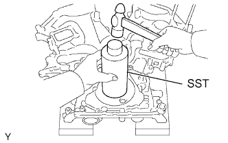 |
Using SST and a hammer, tap in a new oil seal until its surface is flush with the timing chain cover edge.
- SST
- 09226-10010
Apply MP grease to the oil seal lip.
| 2. INSTALL TIMING CHAIN OR BELT COVER SUB-ASSEMBLY |
Remove any old packing (FIPG) material and be careful not to drop any oil on the contact surfaces of the timing chain cover, cylinder head and cylinder block.
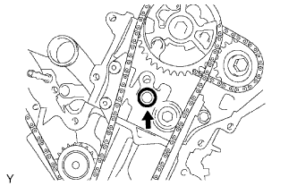
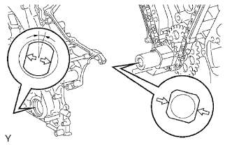
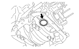
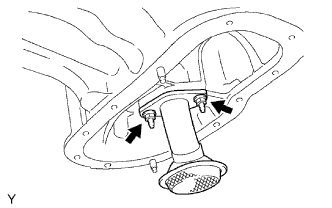
Install a new O-ring onto the LH cylinder head as shown in the illustration.
 |
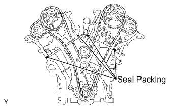
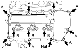
Apply continuous beads of seal packing (diameter 3 to 4 mm (0.12 to 0.16 in.)) to the 4 locations shown in the illustration.
- Seal packing:
- Toyota Genuine Seal Packing Black, Three Bond 1207B or equivalent
 |
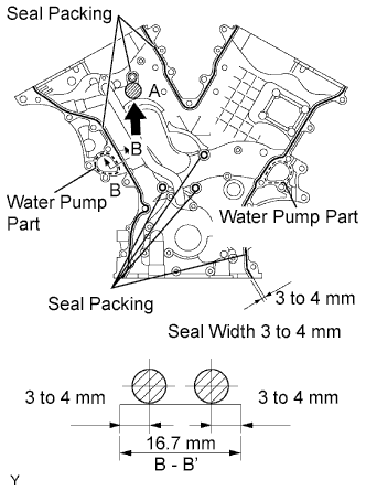
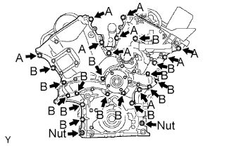
Apply continuous beads of seal packing (diameter 3 to 4 mm (0.12 to 0.16 in.)) to the timing chain cover as shown in the illustration.
- Seal packing:
- Water pump part:
- Toyota Genuine Seal Packing 1282B, Three Bond 1282B or equivalent
- Other parts:
- Toyota Genuine Seal Packing Black, Three Bond 1207B or equivalent
- NOTICE:
- Install the timing chain cover within 3 minutes after applying seal packing. Timing chain cover bolts and nuts must be tightened within 15 minutes of installation. Otherwise the seal packing must be removed and reapplied.
- Do not apply seal packing to portion A shown in the illustration.
 |
Align the key way of the oil pump drive rotor with the rectangular portion of the crankshaft timing gear, and slide the timing chain cover into place.
 |
Install the timing chain cover with the 24 bolts and 2 nuts. Tighten the bolts and nuts uniformly in several steps.
- Torque:
- 23 N*m{ 235 kgf*cm , 17 ft.*lbf }
- NOTICE:
- Pay attention not to wrap the chain and slipper over the timing chain cover seal line.
- Each bolt length is as follows:
Bolt Length A 25 mm (0.98 in.) B 55 mm (2.17 in.)
 |
| 3. INSTALL OIL FILTER BRACKET SUB-ASSEMBLY |
Install a new gasket and oil filter bracket with the 3 bolts and 2 nuts.
- Torque:
- 19 N*m{ 194 kgf*cm , 14 ft.*lbf }
| 4. INSTALL VVT SENSOR |
LH bank side VVT sensor:
Apply a light coat of engine oil to the O-ring of the VVT sensor.
Install the VVT sensor with the bolt.
- Torque:
- 8.0 N*m{ 82 kgf*cm , 71 in.*lbf }
Connect the VVT sensor connector.
Connect the water by-pass hoses No. 4 and No. 5.
RH bank side VVT sensor:
Apply a light coat of engine oil to the O-ring of the VVT sensor.
Install the VVT sensor with the bolt.
- Torque:
- 8.0 N*m{ 82 kgf*cm , 71 in.*lbf }
Connect the VVT sensor connector.
| 5. INSTALL CAMSHAFT TIMING OIL CONTROL VALVE ASSEMBLY |
Install the 2 camshaft timing oil control valves with the 2 bolts.
- Torque:
- 9.0 N*m{ 92 kgf*cm , 80 in.*lbf }
Connect the 2 connectors.
| 6. INSTALL CYLINDER HEAD COVER SUB-ASSEMBLY LH |
Remove any old packing (FIPG) material and be careful not to drop any oil on the contact surfaces of the cylinder head, timing chain cover and cylinder head cover.
Install the cylinder head cover within 3 minutes of applying seal packing. Tighten the cylinder head cover bolts and nuts within 15 minutes of installing the cylinder head cover. Otherwise, the seal packing mush be removed and reapplied.
- Seal packing:
- Toyota Genuine Seal Packing Black, Three Bond 1207B or equivalent
- NOTICE:
- Install the cylinder head cover within 3 minutes after applying the seal packing. After installing it, cylinder head cover bolts and nuts must be tightened within 15 minutes. Otherwise the seal packing must be removed and reapplied.
 |
Install the seal washers onto the bolts.
Install the cylinder head cover with the 10 bolts and 2 nuts. Tighten the bolts and nuts uniformly in several steps.
- Torque:
- 10 N*m{ 102 kgf*cm , 7.4 ft.*lbf } for bolt A
- 9.0 N*m{ 92 kgf*cm , 80 in.*lbf } for bolt B
- 9.0 N*m{ 92 kgf*cm , 80 in.*lbf } for nut
- HINT:
- Each bolt length is as follows.
Bolt Length A 25 mm (0.98 in.) B 60 mm (2.36 in.)
 |
| 7. INSTALL CYLINDER HEAD COVER SUB-ASSEMBLY |
Remove any old packing (FIPG) material and be careful not to drop any oil on the contact surfaces of the cylinder head, timing chain cover and cylinder head cover.
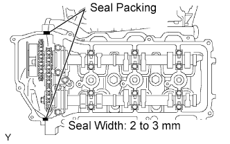
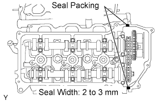
Apply a continuous bead of seal packing (diameter 2 to 3 mm (0.08 to 0.12 in.)) to the cylinder head and timing chain cover as shown in the illustration.
- Seal packing:
- Toyota Genuine Seal Packing Black, Three Bond 1207B or equivalent
- NOTICE:
- Install the cylinder head cover within 3 minutes of applying the seal packing. Tighten the cylinder head cover bolts and nuts within 15 minutes of installing the cylinder head cover. Otherwise, the seal packing must be removed and reapplied.
 |
Install the seal washers onto the bolts.
Install the cylinder head cover with the 10 bolts and 2 nuts. Tighten the bolts and nuts uniformly in several steps.
- Torque:
- 10 N*m{ 102 kgf*cm , 7.4 ft.*lbf } for bolt A
- 9.0 N*m{ 92 kgf*cm , 80 in.*lbf } for bolt B
- 9.0 N*m{ 92 kgf*cm , 80 in.*lbf } for nut
- HINT:
- Each bolt length is as follows.
Bolt Length A 25 mm (0.98 in.) B 60 mm (2.36 in.)
 |
| 8. INSTALL IGNITION COIL ASSEMBLY |
Install the 6 ignition coils with the 6 bolts.
- Torque:
- 10 N*m{ 102 kgf*cm , 7.4 ft.*lbf }
Connect the 6 ignition coil connectors.
| 9. INSTALL INTAKE AIR SURGE TANK |
Install a new gasket and the intake air surge tank with the 2 nuts.
- Torque:
- 28 N*m{ 286 kgf*cm , 21 ft.*lbf }
Using an 8 mm socket hexagon wrench, install the 4 bolts.
- Torque:
- 28 N*m{ 286 kgf*cm , 21 ft.*lbf }
Install the 3 upper bolts which are used to secure the 2 surge tank stays and throttle body bracket.
- Torque:
- 21 N*m{ 214 kgf*cm , 16 ft.*lbf }
Install the 3 wire harness clamps and hose clamp.
Connect the throttle motor connector.
Connect the 2 VSV connectors.
Connect the ventilation hose.
Connect the fuel vapor feed hose.
Connect the water by-pass hose No. 4.
Connect the water by-pass hose No. 5.
| 10. INSTALL OIL PAN SUB-ASSEMBLY |
Remove any old packing (FIPG) material and be careful not to drop any oil on the contact surfaces of the cylinder block, rear oil seal retainer and oil pan.
Install a new O-ring onto the oil pump.
 |
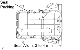
Apply a continuous bead of seal packing (diameter 3 to 4 mm (0.12 to 0.16 in.)) to the oil pan as shown in the illustration.
- Seal packing:
- Toyota Genuine Seal Packing Black, Three Bond 1207B or equivalent
- NOTICE:
- Install the oil pan within 3 minutes of applying the seal packing. Tighten the oil pan bolts and nuts within 15 minutes of installing the oil pan. Otherwise, the seal packing must be removed and reapplied.
 |
Install the oil pan with the 17 bolts and 2 nuts, and tighten the bolts and nuts uniformly in several steps.
- Torque:
- 10 N*m{ 102 kgf*cm , 7.4 ft.*lbf } for 10 mm (0.39 in.) head
- 21 N*m{ 214 kgf*cm , 16 ft.*lbf } for 12 mm (0.47 in.) head
- HINT:
- Each bolt length is as follows:
Bolt Length A 25 mm (0.98 in.) B 45 mm (1.77 in.) C 14 mm (0.55 in.)
 |
Install the 4 housing bolts.
- Torque:
- 37 N*m{ 377 kgf*cm , 27 ft.*lbf }
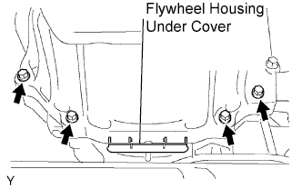 |
Install the flywheel housing under cover.
| 11. INSTALL OIL STRAINER SUB-ASSEMBLY |
 |
Install a new gasket and the oil strainer with the 2 nuts.
- Torque:
- 9.0 N*m{ 92 kgf*cm , 80 in.*lbf }
| 12. INSTALL NO.2 OIL PAN SUB-ASSEMBLY |
Remove any old packing (FIPG) material and be careful not to drop any oil on the contact surfaces of the oil pan and oil pan No. 2.
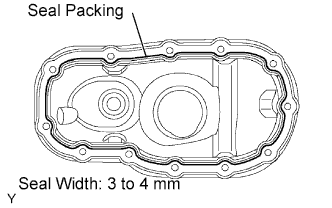
Apply a continuous bead of seal packing (diameter 3 to 4 mm (0.12 to 0.16 in.)) as shown in the illustration.
- Seal packing:
- Toyota Genuine Seal Packing Black, Three Bond 1207B or equivalent
- NOTICE:
- Install the oil pan No. 2 within 3 minutes of applying the seal packing. Tighten the oil pan No. 2 bolts and nuts within 15 minutes of installing the oil pan No. 2. Otherwise, the seal packing must be removed and reapplied.
 |
Install the oil pan No. 2 with the 10 bolts and 2 nuts. Tighten the bolts and nuts uniformly in several steps.
- Torque:
- 9.0 N*m{ 92 kgf*cm , 80 in.*lbf } for bolts
- 10 N*m{ 102 kgf*cm , 7.4 ft.*lbf } for nut
 |
| 13. INSTALL CRANKSHAFT PULLEY |
 |
Using SST, install the pulley set bolt.
- SST
- 09213-54015
(91651-60855)
09330-00021
- Torque:
- 250 N*m{ 2,549 kgf*cm , 184 ft.*lbf }
| 14. INSTALL NO.1 IDLER PULLEY SUB-ASSEMBLY |
 |
Install the idler pulley with the bolt.
- Torque:
- 54 N*m{ 551 kgf*cm , 40 ft.*lbf }
- HINT:
- DOUBLE is marked on the idler pulley No. 1 to distinguish it from the idler pulley No. 2.
| 15. INSTALL NO.2 IDLER PULLEY DUB-ASSEMBLY |
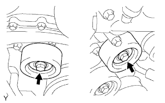 |
Install the 2 idler pulleys with the 2 bolts.
- Torque:
- 54 N*m{ 551 kgf*cm , 40 ft.*lbf }
| 16. INSTALL V-RIBBED BELT TENSIONER ASSEMBLY |
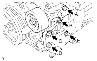 |
- NOTICE:
- A bolt in position A is not reusable.
- HINT:
- Each bolt length is as follows:
| Position | Length |
| A | 70 mm (2.76 in.) |
| B, C, D and E | 33 mm (1.30 in.) |
Use a new bolt in position A.
Finger-tighten the bolts in positions A and E and install the bracket.
Tighten the bolts in positions A and E.
- Torque:
- 36 N*m{ 267 kgf*cm , 27 ft.*lbf }
Tighten the bolts in positions B, C and D.
- Torque:
- 36 N*m{ 267 kgf*cm , 27 ft.*lbf }
| 17. INSTALL COOLER COMPRESSOR ASSEMBLY |
Install the cooler compressor assembly with the 4 bolts.
- Torque:
- 25 N*m{ 255 kgf*cm , 18 ft.*lbf }
Connect the cooler compressor assembly connector.
Install the suction hose sub-assembly with the bolt.
- Torque:
- 8.0 N*m{ 82 kgf*cm , 71 in.*lbf }
| 18. INSTALL GENERATOR ASSEMBLY |
Install the generator assembly with the 2 bolts.
- Torque:
- 43 N*m{ 438 kgf*cm , 32 ft.*lbf }
Install the wire harness clamp bracket with the 2 bolts.
- Torque:
- 8.0 N*m{ 82 kgf*cm , 71 in.*lbf }
Connect the wire harness.
Connect the wire harness to terminal B and install the nut.
- Torque:
- 9.8 N*m{ 100 kgf*cm , 7.0 ft.*lbf }
Connect the connector to the generator assembly.
Install the wire harness stay with the bolt.
- Torque:
- 8.0 N*m{ 82 kgf*cm , 71 in.*lbf }
| 19. INSTALL VANE PUMP ASSEMBLY |
 |
Install the vane pump with the 2 bolts.
Connect the power steering pressure switch connector.
- Torque:
- 43 N*m{ 438 kgf*cm , 32 ft.*lbf }
- NOTICE:
- Do not hit the pulley with other parts when installing the vane pump.
Connect the power steering pressure switch connector.
| 20. INSTALL WATER INLET |
Install a new gasket onto the water inlet with thermostat.
Install the water inlet with thermostat with the 3 nuts.
- Torque:
- 9.0 N*m{ 92 kgf*cm , 80 in.*lbf }
| 21. INSTALL OIL LEVEL GAUGE GUIDE |
| 22. INSTALL AIR TUBE ASSEMBLY (w/ Secondary Air Injection System) |
Install the air tube assembly with the bolt.
- Torque:
- 10 N*m{ 102 kgf*cm , 7 ft.*lbf }
Connect the 2 wire harness clamps.
Install the bolt.
- Torque:
- 8.0 N*m{ 82 kgf*cm , 71 in.*lbf }
| 23. INSTALL AIR SWITCHING VALVE ASSEMBLY (w/ Secondary Air Injection System) |
| 24. INSTALL NO. 2 AIR CLEANER HOSE (w/ Secondary Air Injection System) |
Install the No. 2 air cleaner hose with the 2 bolts.
- Torque:
- 12 N*m{ 122 kgf*cm , 9 ft.*lbf }
| 25. INSTALL AIR PUMP ASSEMBLY (w/ Secondary Air Injection System) |
| 26. INSTALL AIR CLEANER ASSEMBLY |
Install the air cleaner with the 2 bolts.
- Torque:
- 8.0 N*m{ 82 kgf*cm , 71 in.*lbf }
Connect the ventilation hose No. 2.
| 27. INSTALL FAN SHROUD |
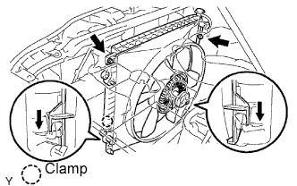 |
Provisionally install the fan shroud together with the fan pulley.
Install the fan and generator V belt (Click here).
Install the fan pulley with the 4 nuts.
- Torque:
- 21 N*m{ 214 kgf*cm , 16 ft.*lbf }
Install the fan shroud with the 2 bolts.
- Torque:
- 5.0 N*m{ 51 kgf*cm , 48 in.*lbf }
Install the 2 cooler hoses into the clamp (with automatic transmission).
Connect the hose to the radiator reserve tank.
| 28. INSTALL RADIATOR SUPPORT TO FRAME SEAL LH |
| 29. INSTALL FRONT DIFFERENTIAL CARRIER ASSEMBLY |
| 30. INSTALL POWER STEERING LINK ASSEMBLY |
| 31. INSTALL BATTERY |
| 32. ADD ENGINE OIL |
Fill with fresh engine oil.
- Standard engine oil:
Oil grade Oil viscosity (SAE) ILSAC multigrade engine oil 5W-30
- Standard capacity (for 2WD):
Item Specified Condition Drain and refill with oil filter change 4.5 liters (4.8 US qts, 4.0 lmp. qts) Drain and refill without oil filter change 4.2 liters (4.4 US qts, 3.7 lmp. qts) Dry fill 5.6 liters (5.9 US qts, 4.9 lmp. qts)
- Standard capacity (for PRE RUNNER and 4WD):
Item Specified Condition Drain and refill with oil filter change 5.2 liters (5.5 US qts, 4.6 lmp. qts) Drain and refill without oil filter change 4.9 liters (5.2 US qts, 4.3 lmp. qts) Dry fill 6.0 liters (6.3 US qts, 5.3 lmp. qts)
Reinstall the oil filler cap.
| 33. ADD ENGINE COOLANT |
Pour coolant into the radiator until it overflows.
- Capacity:
Transmission Capacity Manual Transmission 9.7 liters (10.3 Us qts, 8.5 Imp. qts) Automatic Transmission 9.8 liters (10.4 Us qts, 8.6 Imp. qts)
- HINT:
- Use of improper coolants may damage the engine cooling system.
- Use only Toyota Super Long Life Coolant or similar high quality ethylene glycol based non-silicate, non-amine, non-nitrite, and non-borate coolant with long-life hybrid organic acid technology (coolant with long-life hybrid organic acid technology consists of a combination of low phosphates and organic acids).
- New Toyota vehicles are filled with Toyota Super Long Life Coolant (color is pink, premixed ethylene glycol concentration is approximately 50 % and freezing temperature is -35°C (-31°F)). When replacing the coolant, Toyota Super Long Life Coolant is recommended.
- NOTICE:
- Do not substitute plain water for engine coolant.
Check the coolant level inside the radiator by squeezing the inlet and outlet radiator hoses several times by hand. If the coolant level goes down, add coolant.
Install the radiator cap securely.
Slowly pour coolant into the radiator reservoir until it reaches the FULL line.
Warm up the engine until the cooling fan operates.
Set the air conditioning as follows while warming up the engine.
Item Condition Fan Speed Any setting except OFF Temperature Toward WARM Air Conditioning Switch OFF Maintain the engine speed at 2,000 to 2,500 rpm and warm up the engine until the cooling fan operates.
Squeeze the inlet and outlet radiator hoses several times by hand while warming up the engine.
Stop the engine and wait until the coolant cools down.
Remove the radiator cap and check the coolant level inside the radiator.
If the coolant level is below the full level, perform the steps from (a) through (h) and repeat the operation until the coolant level remains at the full level.
Check the coolant level inside the radiator reservoir tank again. If it is below the full level, add coolant.
| 34. ADD DIFFERENTIAL OIL (for 4WD) |
| 35. INSPECT DIFFERENTIAL OIL (for 4WD) |
 |
Stop the vehicle on a level place.
Remove the differential filler plug and gasket.
Check that the oil level is within 5 mm (0 to 0.20 in.) of the bottom of the filler plug opening.
- NOTICE:
- Excessively large or small quantities of oil may cause problems.
- After replacing the oil, drive the vehicle and check the oil level again.
- HINT:
- If necessary, fill the differential carrier assembly with differential gear oil.
- Oil type and viscosity:
- Toyota Genuine Differential gear oil LT APL 75W-85 GL-5 or equivalent.
- Capacity:
- Front differential carrier assembly:
- 1.45 to 1.55 liters
- (1.54 to 1.64 US qts, 1.28 to 1.36 lmp. qts)
- Rear differential carrier assembly (for 2WD):
- 3.26 to 3.36 liters
- (3.45 to 3.55 US qts, 2.87 to 2.95 lmp. qts)
- Rear differential carrier assembly (for Pre, 4WD):
- 2.75 to 2.85 liters
- (2.91 to 3.01 US qts, 2.42 to 2.50 lmp. qts)
Check for oil leakage if the oil level is low.
Install the differential filler plug and a new gasket.
- Torque:
- Front differential carrier assembly:
- 39 N*m{ 398 kgf*cm , 29 ft.*lbf }
- Rear differential carrier assembly:
- 49 N*m{ 500 kgf*cm , 36 ft.*lbf }
| 36. ADD POWER STEERING FLUID |
 |
Keep the vehicle level.
With the engine stopped, check the fluid level in the oil reservoir.
If necessary, add fluid.- Fluid:
- ATF "DEXRON" II or III
- HINT:
- Check that the fluid level is within the HOT level range in the reservoir tank. If the fluid is cold, check that it is within the COLD level range.
Start the engine and let it idle.
Turn the steering wheel from lock to lock several times to raise fluid temperature.
- Fluid temperature:
- 75 to 80°C (167 to 176°F)
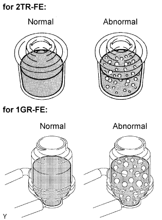
Check for foaming or emulsification.
If any foaming or emulsification is identified, bleed the power steering system.
 |
With the engine idling, measure the fluid level in the oil reservoir.
 |
Stop the engine.
Wait a few minutes and measure the fluid level in the oil reservoir again.
- Maximum fluid level rise:
- 5 mm (0.20 in.)
Check the fluid level.
| 37. BLEED POWER STEERING FLUID |
Check the fluid level.
Jack up the front of the vehicle and support it with stands.
Turn the steering wheel.
With the engine stopped, turn the wheel slowly from lock to lock several times.
Lower the vehicle.
Start the engine.
Run the engine at idle for a few minutes.
Turn the steering wheel.
With the engine idling, turn the wheel to the left or right full lock position and keep it there for 2 to 3 seconds. Then turn the wheel to the opposite full lock position and keep it there for 2 to 3 seconds (step A).
Repeat step A several times.
Stop the engine.
Check for foaming or emulsification.
Especially, if the system has to be bled twice because of foaming or emulsification, check for fluid leakage in the system.
|
Check the fluid level.
| 38. CHECK FOR ENGINE OIL LEAKAGE |
| 39. CHECK FOR ENGINE COOLANT LEAKAGE |
Fill the radiator with coolant and attach a radiator cap tester.
Pump it to 118 kPa (1.2 kgf/cm2 17.1 psi), then check for leakage.
| 40. CHECK FOR FUEL LEAKAGE |
| 41. CHECK FOR EXHAUST GAS LEAKAGE |
| 42. CHECK POWER STEERING FLUID LEAKAGE |
| 43. INSPECT AND ADJUST FRONT WHEEL ALIGNMENT |
| 44. INSTALL V-BANK COVER |
Install the V-bank cover with the 2 nuts.
- Torque:
- 7.5 N*m{ 76 kgf*cm , 66 in.*lbf }
| 45. INSPECT IGNITION TIMING |
- NOTICE:
- Turn all electrical systems OFF.
- Operate the inspection when the cooling fan motor is turned OFF.
Warm up the engine.
When using the Techstream.
Connect the Techstream to the DLC3.
Enter the following menu items:
Select: Powertrain / Engine and ECT / Data List / IGN Advance.Inspect the ignition timing during idling.
- Ignition timing:
- 7 to 24° BTDC @ idle (Transmission in neutral position)
Check that the ignition timing advances immediately when the engine speed is increased.
When not using Techstream.
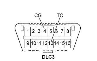
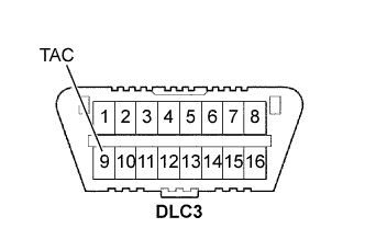
Using SST, connect the terminals 13 (TC) and 4 (CG) of the DLC3.
- SST
- 09843-18040
- NOTICE:
- Be sure not to connect the terminals wrongly. It causes breakage of the engine.
Remove the air cleaner.
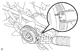
Pull out the wire harness as shown in the illustration.
Connect the tester probe of a timing light to the wire of the ignition coil connector for No. 1 cylinder.
- NOTICE:
- Use a timing light that detects the first signal.
- After checking, be sure to wrap the wire harness with tape.
Inspect the ignition timing during idling.
- Ignition timing:
- 8 to 12° BTDC @ idle (Transmission in neutral position)
Remove the SST from the DLC3.
Inspect the ignition timing during idling.
- Ignition timing:
- 7 to 24° BTDC @ idle (Transmission in neutral position)
Install the air cleaner.

 |
| 46. INSPECT ENGINE IDLING SPEED |
- NOTICE:
- Turn all the electrical systems OFF.
- Operate the inspection when the cooling fan motor is turned OFF.
Warm up the engine.
When using the Techstream:
Connect the Techstream to the DLC3.
Enter the following menu items:
Select: Powertrain / Engine and ECT / Data List / Engine Speed.Inspect the engine idling speed.
- Idling speed:
- 650 to 750 rpm (Transmission in neutral position)
When not using the Techstream:
Using SST, connect the terminal 8 (TAC) of the DLC3.
- SST
- 09843-18030
Race the engine speed at 2,500 rpm for approximately 90 seconds.
Inspect the engine idling speed.
- Idling speed:
- 650 to 750 rpm (Transmission in neutral position)
 |
| 47. INSPECT COMPRESSION |
Warm up and stop the engine.
Remove the circuit opening relay.
Remove the V-bank cover.
Remove the air cleaner assembly.
Remove the ignition coils.
Remove the spark plugs.
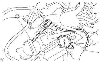
Inspect the cylinder compression pressure.
Insert a compression gage into the spark plug hole.
- SST
- 09992-00500
Fully open the throttle.
While cranking the engine, measure the compression pressure.
- Compression pressure:
- 1,300 kPa (13.3 kgf/cm2, 189 psi)
- Minimum pressure:
- 1,000 kPa (10.2 kgf/cm2, 145 psi)
- Difference between each cylinder:
- 100 kPa (1.0 kgf/cm2, 15 psi)
- NOTICE:
- Use a fully-charged battery so the engine speed can be increased to 250 rpm or more.
- Inspect the other cylinders in the same way.
- Measure the compression in as short a time as possible.
If the cylinder compression is low, pour a small amount of engine oil into the cylinder through the spark plug hole and repeat steps (1) through (3) for cylinders with low compression.
- If adding oil increases the compression, the piston rings and/or cylinder bore may be worn or damaged.
- If pressure stays low, a valve may be stuck or seated improperly, or there may be leakage from the gasket.
- If adding oil increases the compression, the piston rings and/or cylinder bore may be worn or damaged.
 |
| 48. INSPECT CO/HC |
Start the engine.
Run the engine at 2,500 rpm for approximately 180 seconds.
Insert the CO/HC meter testing probe at least 40 cm (1.3 ft) into the tailpipe during idling.
Immediately check the CO/HC concentration during idling and/or at 2,500 rpm.
- HINT:
- Complete the measurement within 3 minutes.
- When carrying out the 2 modes (idling and 2,500 rpm) test, the measurement orders are prescribed by the applicable local regulations.
If the CO/HC concentration does not comply with regulations, troubleshoot in the order given below.
Check the heated oxygen sensor operation.
CO HC Problems Causes Normal High Rough idling - Faulty ignition:
- Incorrect timing
- Fouled, shorted or improperly gapped plugs
- Incorrect valve clearance
- Leaky intake and exhaust valves
- Leaky cylinders
Low High Rough idling
(Fluctuating HC reading)- Vacuum leaks:
- PCV hoses
- Intake manifold
- Throttle body
- IAC valve
- Brake booster line
- Lean mixture causing misfire
High High Rough idling
(Black smoke from exhaust)- Restricted air filter
- Plugged PCV valve
- Faulty EFI systems:
- Faulty pressure regulator
- Faulty engine coolant temperature sensor
- Faulty mass air flow meter
- Faulty ECM
- Faulty injectors
- Faulty throttle position sensor
- Faulty ignition: