EMISSION CONTROL SYSTEM (w/o Secondary Air Injection System) > ON-VEHICLE INSPECTION |

for Preparation Click here
| 1. INSPECT AIR-FUEL RATIO COMPENSATION SYSTEM |

Measure the voltage according to the value(s) in the table below.
- Standard Voltage:
Tester Connection Switch Condition Specified Condition E11-1 (A1A+) - E11-12 (E1) Ignition switch ON 3.3 V E11-7 (A2A+) - E11-12 (E1) Ignition switch ON 3.3 V E11-2 (A1A-) - E11-12 (E1) Ignition switch ON 2.9 V E11-8 (A2A-) - E11-12 (E1) Ignition switch ON 2.9 V
- NOTICE:
- Connect test leads from the back side of the connector. Do not disconnect the connectors from the ECM.
- HINT:
- Voltage between the terminals of the ECM is kept constant regardless of the voltage of the A/F sensor.
Connect the Techstream to the DLC3.
Turn the ignition switch to ON.
Turn the Techstream on.
Enter the following menus: Powertrain / Engine and ECT / Data List / "AFS Voltage B1 S1", "AFS Voltage B2 S1", "Short FT #1" and "Short FT #2".
Warm up the air fuel ratio sensor with the engine speed at 2,500 rpm for approximately 2 minutes.
Rev the engine several times and confirm that the value of "Short FT #1 (Short FT #2)" changes in response to the value of "AFS Voltage B1 S1 (AFS Voltage B2 S1)".
- OK:
- The "Short FT #1 (Short FT #2)" changes in response to the "AFS Voltage B1 S1 (AFS Voltage B2 S1)".
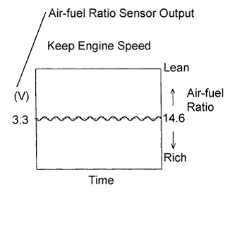
Maintain the engine speed at 2,500 rpm and confirm that the display on the Techstream, when AFS Voltage B1 S1 is selected, is as shown in the illustration.
- HINT:
- The illustration may slightly differ from the display on the Techstream.
- Only the Techstream displays the waveform of the air fuel ratio sensor.
- CAUTION:
- Perform the check immediately after warming up the engine.
- If the voltage variation could not be verified, warm up the air fuel ratio sensor again. If it could not be verified even after warming up the sensor again, check the DTC No. (Click here).
 |
| 2. INSPECT FUEL CUT OFF RPM |
Start and warm up the engine.
Open the throttle valve and keep the engine speed at 3,500 rpm.
Use a sound scope to check for injector operating sounds.
Check that when the accelerator pedal is released, injector operating noise stops momentarily and then resumes.
If the result is as not specified, check the injector, wiring and ECM.
| 3. VISUALLY INSPECT HOSES, CONNECTIONS AND GASKETS |
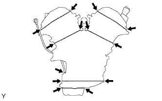 |
Check the appearance.
Check if the indicated portions of the engine assembly are cracked, leaking or damaged.
- HINT:
- Disconnection of the engine oil level gauge, oil filler cap, PCV hose, etc. may cause the engine to run improperly. Disconnected, loose or cracked parts in the air induction system between the throttle body and cylinder head will allow air suction and cause the engine to run improperly.
| 4. INSPECT FUEL CUTOFF VALVE AND FILL CHECK VALVE |
 |
Remove the fuel tank (Click here).
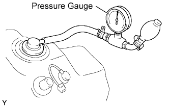
Connect the pressure gauge to the vent hose port.
Install the fuel tank with the vent hose disconnected.
Fill the fuel tank with fuel.
Apply pressure at 4 kPa (41 kgf/cm2, 0.58 psi) to the vent port of the fuel tank.
- HINT:
- Check the amount of fuel left in the fuel tank.
Remove the fuel tank cap, and check that the pressure decreases.
If the pressure does not decrease, replace the fuel tank assembly.
 |
Reconnect the vent line hose to the fuel tank.
| 5. CHECK AIR INLET LINE |
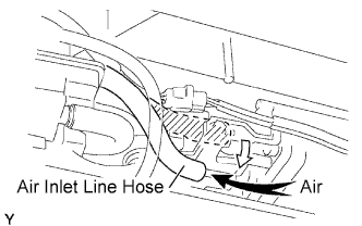 |
Disconnect the air inlet line hose from the charcoal canister.
Check that air flows freely into the air inlet line.
If air does not flow freely into the air inlet line, repair or replace the air inlet line.
Reconnect the air inlet line hose to the charcoal canister.
| 6. INSPECT CANISTER PUMP MODULE (Pressure Sensor) |

Check the power source voltage for pressure sensor.
Measure the voltage according to the value(s) in the table below.
- Standard Voltage:
Tester Connection Switch Condition Specified Condition E9-15 (VCV1) - E10-8 (ETHW) Ignition switch ON 4.5 to 5.0 V
Check the output voltage of pressure sensor.
Remove the fuel tank cap.
Measure the voltage according to the value(s) in the table below.
- Standard Voltage:
Tester Connection Switch Condition Specified Condition E10-1 (PPMP) - E10-8 (ETHW) Ignition switch ON 3.0 to 3.6 V
Install the fuel tank cap.