REAR DOOR (for Access Cab) > REASSEMBLY |

for Preparation Click here
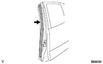
| 1. INSTALL REAR DOOR WEATHERSTRIP LH |
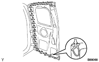 |
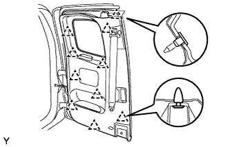
Engage the 20 clips and install a new rear door weatherstrip LH.
Engage the 3 clips.
 |
Remove the tab tape at both ends of the 2-sided tape attached to the weather strip, and attach the weather strip to the door panel with the 2-sided tape.
| 2. INSTALL REAR DOOR CHECK ASSEMBLY LH |
 |
Apply MP grease to the sliding areas of the check assembly.
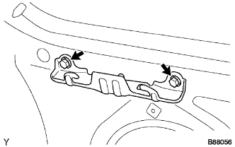
Install the access panel check assembly LH onto the door panel with the 2 nuts.
- Torque:
- 5.5 N*m{ 56 kgf*cm , 49 in.*lbf }
Apply adhesive to the threads of the bolt.
- NOTICE:
- Toyota Genuine Adhesive 1324, Three Bond 1324 or equivalent
Install the access panel check assembly LH onto the body panel with the bolt.
- Torque:
- 30 N*m{ 306 kgf*cm , 22 ft.*lbf }
| 3. INSTALL REAR DOOR SERVICE HOLE COVER LH |
 |
Install a new rear door service hole cover LH.
- HINT:
- After attaching the service hole cover, check the quality of the seal.
| 4. INSTALL FRONT DOOR LOCK STRIKER PLATE ASSEMBLY |
 |
Using a "TORX" socket wrench T40, install the door lock striker plate assembly with the 2 screws.
- Torque:
- 23 N*m{ 235 kgf*cm , 17 ft.*lbf }
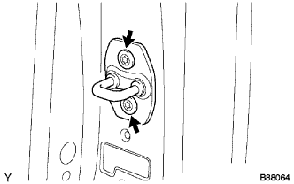
| 5. INSTALL FRONT DOOR COURTESY LIGHT SWITCH ASSEMBLY |
Install the front door courtesy light switch with the bolt.
- Torque:
- 9.0 N*m{ 92 kgf*cm , 80 in.*lbf }
 |
Connect the connector.
| 6. INSTALL REAR DOOR INSIDE LOCKING CABLE ASSEMBLY LH |
 |
Using a "TORX" socket wrench T25, install the access panel lock cancel lever assembly LH with the 2 screws.
- Torque:
- 5.0 N*m{ 51 kgf*cm , 44 in.*lbf }
| 7. INSTALL ACCESS PANEL LOCK REMOTE CONTROL ASSEMBLY LH |
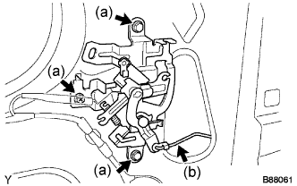 |
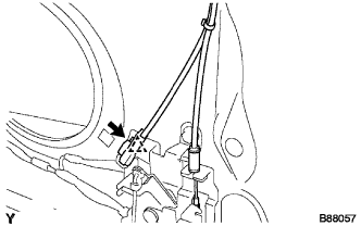
Install the access panel lock remote control assembly LH with the 2 bolts and the screw.
- Torque:
- 12 N*m{ 122 kgf*cm , 9 ft.*lbf }
Connect the rod.
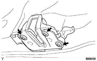
| 8. INSTALL ACCESS PANEL LOWER LOCK ASSEMBLY LH |
 |
Install the access panel lower lock assembly LH onto the access door.
Connect the connector and access lock control cable sub-assembly.
Using a "TORX" socket wrench T30, install the 3 screws.
- Torque:
- 5.0 N*m{ 51 kgf*cm , 44 in.*lbf }
 |
| 9. INSTALL ACCESS PANEL UPPER LOCK ASSEMBLY LH |
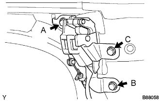 |
Provisionally install the access panel upper lock assembly LH with the 3 bolts.
Tighten the 3 bolts in the order A to C as indicated.
- Torque:
- 12 N*m{ 122 kgf*cm , 9 ft.*lbf }
Connect the connector, connector clamp and access lock control cable sub-assembly.
 |
| 10. INSTALL NO. 1 DOOR TRIM BRACKET RH |
 |
Install the No. 1 door trim bracket with the 2 screws.
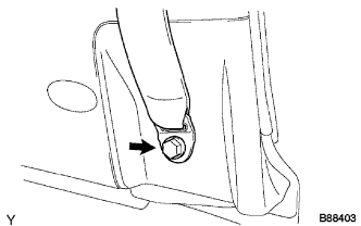
| 11. INSTALL FRONT SHOULDER BELT ANCHOR ADJUSTER ASSEMBLY |
Insert the 2 claws of the front shoulder belt anchor adjuster into the hole in the body and mount the bolt.
- Torque:
- 42 N*m{ 430 kgf*cm , 31 ft.*lbf }
 |
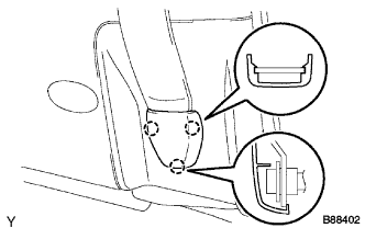
| 12. INSTALL FRONT SEAT OUTER BELT ASSEMBLY LH |
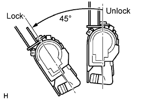
Check the amount of inclination required to lock the retractor.
Gently incline the retractor from its initial position. Check that the belt does not lock when the retractor is inclined 15° or less in any directions. Also check that the belt locks when the inclination of the retractor is 45° or more.
- NOTICE:
- Do not disassemble the retractor.
 |
Hook the lower stay of the retractor onto the 2 body hooks.
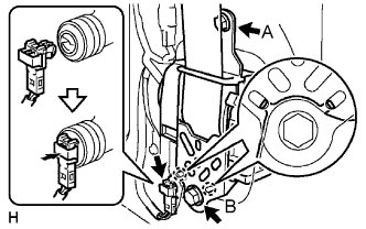 |
Tighten bolt A, and then tighten bolt B.
- Torque:
- 8.5 N*m{ 85 kgf*cm , 75 in.*lbf } for bolt A
- 42 N*m{ 430 kgf*cm , 31 ft.*lbf } for bolt B
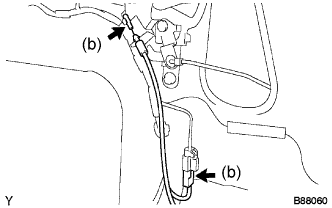
Connect the pretensioner connector as shown in the illustration.
Install the shoulder anchor with the nut.
- Torque:
- 42 N*m{ 430 kgf*cm , 31 ft.*lbf }
 |
Check that the shoulder anchor rotates smoothly.
Install the floor anchor of the front seat outer belt with the bolt.
 |
Check the ELR lock.
- NOTICE:
- The check should be performed with the front seat outer belt installed.
- Do not allow the anchor part of the front seat belt outer and the protruding parts of the door panel to overlap.
With the belt installed, check that the belt locks when it is pulled out quickly.
If operation is not as specified, replace the front seat outer belt.
Remove the bolt and floor anchor.
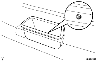
| 13. INSTALL ACCESS PANEL INSIDE HANDLE SUB-ASSEMBLY LH |
 |
Install the access panel inside handle sub-assembly LH with the 3 screws.
Connect the rod.
| 14. INSTALL REAR DOOR TRIM BOARD SUB-ASSEMBLY LH |
 |
Install the rear door trim board sub-assembly LH.
Install the door pull handle with the screw.
 |
Install the access panel inside handle bezel LH with the screw.
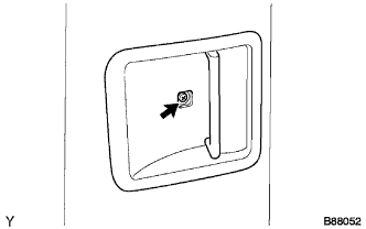 |
Close the cover.
Install the outer front seat belt assembly LH (floor side) with the bolt.
- Torque:
- 42 N*m{ 428 kgf*cm , 31 ft.*lbf }
 |
| 15. INSTALL LAP BELT OUTER ANCHOR COVER |
 |
Engage the 3 claws and install the lap belt outer anchor cover.
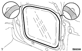
| 16. INSTALL ACCESS PANEL REAR WEATHERSTRIP LH |
 |
Install the access panel rear weatherstrip LH.