ENGINE IMMOBILISER SYSTEM > ECU Power Source Circuit |

for Preparation Click here
DESCRIPTION
This circuit provides power to operate the transponder key ECU assembly.WIRING DIAGRAM
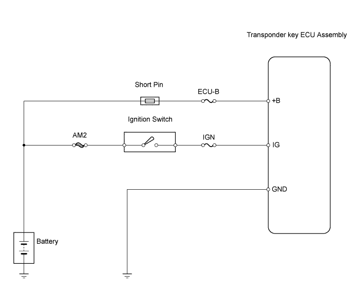
INSPECTION PROCEDURE
| 1.INSPECT FUSES (ECU-B AND IGN) |
Remove the ECU-B fuse from the engine room R/B and J/B.
Remove the IGN fuse from the driver side J/B.
Measure the resistance of the fuse.
- Standard resistance:
- Below 1Ω
Reinstall fuses.
|
| ||||
| OK | |
| 2.INSPECT IGNITION SWITCH ASSEMBLY |
Remove the ignition switch.
 |
Measure the resistance of the switch.
- Standard resistance:
Tester Connection Switch Condition Specified Condition 5 (AM2) - 6 (IG2) LOCK, ACC 10 kΩ or higher ON, START Below 1 Ω
|
| ||||
| OK | |
| 3.CHECK HARNESS AND CONNECTOR (TRANSPONDER KEY ECU ASSEMBLY - BATTERY AND BODY GROUND) |
Disconnect the T10 ECU connector.
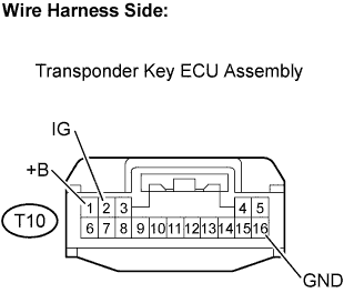 |
Measure the resistance and voltage of the wire harness side connector.
- Standard resistance:
Tester Connection Condition Specified Condition T10-16 (GND) - Body ground Always Below 1 Ω
- Standard voltage:
Tester Connection Condition Specified Condition T10-1 (+B) - Body ground Always 10 to 14 V T10-2 (IG) - Body ground Ignition switch OFF Below 1 V Ignition switch ON 10 to 14 V
Reconnect the ECU connector.
|
| ||||
| OK | ||
| ||