POWER WINDOW CONTROL SYSTEM > Rear Power Window LH does not Operate with Rear Power Window Switch LH |

for Preparation Click here
DESCRIPTION
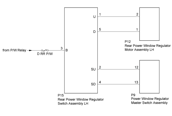
If the rear LH side manual UP / DOWN function does not operate, a malfunction may exist in the rear power window regulator motor assembly LH, rear power window regulator switch assembly LH, power window regulator master switch assembly or wire harness.WIRING DIAGRAM
INSPECTION PROCEDURE
- NOTICE:
- Inspect the fuses for circuits related to this system before performing the following inspection procedure.
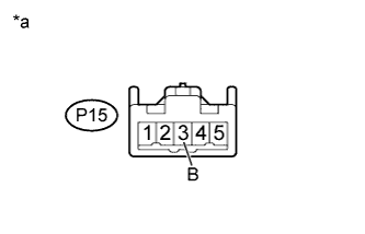
| 1.INSPECT REAR POWER WINDOW REGULATOR SWITCH ASSEMBLY LH |
Remove the rear power window regulator switch assembly LH.
Measure the resistance according to the value(s) in the table below.
- Standard Resistance:
Tester Connection Switch Condition Specified Condition 1 (U) - 3 (B)
4 (SD) - 5 (D)UP Below 1 Ω 2 (SU) - 1 (U)
4 (SD) - 5 (D)OFF Below 1 Ω 2 (SU) - 1 (U)
3 (B) - 5 (D)DOWN Below 1 Ω
Text in Illustration *a Component without harness connected
(Power Window Regulator Switch Assembly LH)
 |
|
| ||||
| OK | |
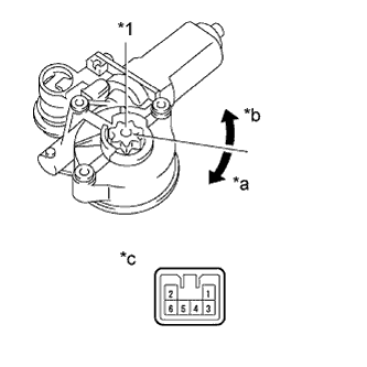
| 2.INSPECT REAR POWER WINDOW REGULATOR MOTOR ASSEMBLY LH |
Remove the rear power window regulator motor assembly LH.
Apply battery voltage to connector terminals 1 and 2.
Check that the motor smoothly rotates.
- NOTICE:
- Do not apply battery voltage to any terminals except terminals 1 and 2.
- OK:
Measurement Condition Specified Condition Battery positive (+) → 2
Battery negative (-) → 1Motor gear rotates clockwise Battery positive (+) → 1
Battery negative (-) → 2Motor gear rotates counterclockwise
Text in Illustration *1 Motor Gear *a Clockwise *b Counterclockwise *c Component without harness connected
(Rear Power Window Regulator Motor Assembly LH)
 |
|
| ||||
| OK | |
| 3.CHECK HARNESS AND CONNECTOR (REAR POWER WINDOW REGULATOR SWITCH ASSEMBLY LH - P/W RELAY) |
 |
Disconnect the P15 rear power window regulator switch assembly LH connector.
Measure the voltage according to the value(s) in the table below.
- Standard Voltage:
Tester Connection Switch Condition Specified Condition P15-3 (B) - Body ground Ignition switch ON 11 to 14 V
Text in Illustration *a Front view of wire harness connector
(to Rear Power Window Regulator Switch Assembly LH)
|
| ||||
| OK | |
| 4.CHECK HARNESS AND CONNECTOR (REAR POWER WINDOW REGULATOR SWITCH ASSEMBLY LH - REAR POWER WINDOW REGULATOR MOTOR ASSEMBLY LH) |
Disconnect the P15 rear power window regulator switch assembly LH connector.
Disconnect the P12 rear power window regulator motor assembly LH connector.
Measure the resistance according the value(s) in the table below.
- Standard Resistance:
Tester Connection Condition Specified Condition P15-1 (U) - P12-2 Always Below 1 Ω P15-5 (D) - P12-1 Always Below 1 Ω P15-1 (U) - Body ground Always 10 kΩ or higher P15-5 (D) - Body ground Always 10 kΩ or higher
|
| ||||
| OK | |
| 5.CHECK HARNESS AND CONNECTOR (REAR POWER WINDOW REGULATOR SWITCH ASSEMBLY LH - POWER WINDOW REGULATOR MASTER SWITCH ASSEMBLY) |
Disconnect the P15 rear power window regulator switch assembly LH connector.
Disconnect the P9 power window regulator master switch assembly connector.
Measure the resistance according to the value(s) in the table below.
- Standard Resistance:
Tester Connection Condition Specified Condition P15-2 (SU) - P9-12 Always Below 1 Ω P15-4 (SD) - P9-13 Always Below 1 Ω P15-2 (SU) - Body ground Always 10 kΩ or higher P15-4 (SD) - Body ground Always 10 kΩ or higher
|
| ||||
| OK | ||
| ||