DTC B1815/54 Short in Front Passenger Side Squib 2nd Step Circuit |
DTC B1816/54 Open in Front Passenger Side Squib 2nd Step Circuit |
DTC B1817/54 Short to GND in Front Passenger Side Squib 2nd Step Circuit |
DTC B1818/54 Short to B+ in Front Passenger Side Squib 2nd Step Circuit |

for Preparation Click here
DESCRIPTION
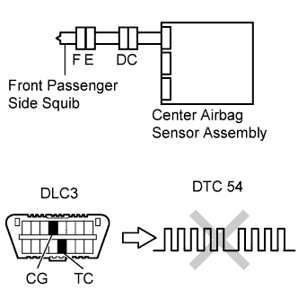
The front passenger side squib (Dual stage -2nd step) circuit consists of the center airbag sensor assembly and the front passenger airbag assembly.The circuit signals the SRS to deploy when airbag deployment conditions are met.
These DTCs are set when a malfunction is detected in the front passenger side squib (Dual stage - 2nd step) circuit.
| DTC No. | DTC Detecting Conditions | Trouble Areas |
| B1815/54 |
|
|
| B1816/54 |
|
|
| B1817/54 |
|
|
| B1818/54 |
|
|
WIRING DIAGRAM

INSPECTION PROCEDURE
- CAUTION:
- In order to prevent unexpected airbag deployment, disconnect the following connectors before inspecting parts such as wire harnesses, if the application of tester probes to the center airbag sensor assembly connector is necessary.
- (a) Turn the ignition switch to the LOCK position.
- (b) Disconnect the negative (-) terminal cable from the battery, and wait for at least 90 seconds.
- (c) Disconnect the connectors from the center airbag sensor assembly.
- (d) Disconnect the connectors from the steering pad.
- (e) Disconnect the connector from the front passenger airbag assembly.
- (f) Disconnect the connector from the front seat airbag assembly LH.
- (g) Disconnect the connector from the front seat airbag assembly RH.
- HINT:
- Skip the following steps if side and curtain shield airbags are not fitted.
- (h) Disconnect the connector from the curtain shield airbag assembly LH.
- (i) Disconnect the connector from the curtain shield airbag assembly RH.
- (j) Disconnect the connector from the front seat outer belt assembly LH.
- (k) Disconnect the connector from the front seat outer belt assembly RH.
| 1.CHECK DTC OUTPUT |
Proceed to the appropriate step according to the DTC readings.
If using the Techstream (read the 5-digit DTCs): Using the Techstream, check for DTCs (Click here).
- Result:
Result Proceed to DTC B1815 is output. A DTC B1816 is output. B DTC B1817 is output. C DTC B1818 is output. D
If not using the Techstream (read the 2-digit DTCs): Check for DTCs (Click here).
- Result:
Result Proceed to DTC 54 is output. E
|
| ||||
|
| ||||
|
| ||||
|
| ||||
| A | |
| 2.CHECK CONNECTOR |
Turn the ignition switch to the LOCK position.
Disconnect the negative (-) terminal cable from the battery, and wait for at least 90 seconds.
Check that the instrument panel wire assembly connectors (on the front passenger airbag assembly side) are not damaged.
- OK:
- The lock button is not disengaged, and the claw of the lock is not deformed or damaged.
|
| ||||
| OK | |
| 3.CHECK CONNECTION OF CONNECTORS |
Check that the connectors are properly connected to the center airbag sensor assembly and the instrument panel wire assembly.
- OK:
- The connectors are properly connected.
|
| ||||
| OK | |
| 4.CHECK INSTRUMENT PANEL WIRE ASSEMBLY (FOR SHORT) |
Disconnect the instrument panel wire assembly connectors from the instrument panel wire and front passenger airbag assembly.
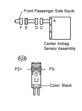 |
Release the activation prevention mechanism built into connector D (Click here).
Measure the resistance.
- Standard resistance:
Tester Connection Condition Specified Condition A24-1 (P2+) - A24-2 (P2-) Always 1 MΩ or Higher
|
| ||||
| OK | |
| 5.CHECK INSTRUMENT PANEL WIRE (FOR SHORT) |
Disconnect the instrument panel wire connector from the center airbag sensor assembly.
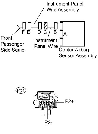 |
Release the activation prevention mechanism built into connector B (Click here).
Measure the resistance.
- Standard resistance:
Tester Connection Condition Specified Condition IG1-1 (P2+) - IG1-2 (P2-) Always 1 MΩ or Higher
|
| ||||
| OK | |
| 6.CHECK CENTER AIRBAG SENSOR ASSEMBLY |
Connect the instrument panel wire connectors to the center airbag sensor assembly and instrument panel wire assembly.
 |
Connect the negative (-) terminal cable to the battery, and wait for at least 2 seconds.
Turn the ignition switch to the ON position, and wait for at least 60 seconds.
Clear any DTCs stored in the memory (Click here).
Turn the ignition switch to the LOCK position.
Turn the ignition switch to the ON position, and wait for at least 60 seconds.
Check for DTCs (Click here).
- OK:
- DTC B1815 is not output.
- HINT:
- DTCs other than B1815 may be output at this time, but they are not related to this check.
|
| ||||
| NG | ||
| ||
| 7.CHECK CONNECTOR |
Turn the ignition switch to the LOCK position.
Disconnect the negative (-) terminal cable from the battery, and wait for at least 90 seconds.
Check that the instrument panel wire assembly connectors (on the front passenger airbag assembly side) are not damaged.
- OK:
- The lock button is not disengaged, and the claw of the lock is not deformed or damaged.
|
| ||||
| OK | |
| 8.CHECK CONNECTION OF CONNECTORS |
Check that the connectors are properly connected to the center airbag sensor assembly and the instrument panel wire assembly.
- OK:
- The connectors are properly connected.
|
| ||||
| OK | |
| 9.CHECK INSTRUMENT PANEL WIRE ASSEMBLY (FOR OPEN) |
Disconnect the instrument panel wire assembly connectors from the instrument panel wire and steering pad.
|
Measure the resistance.
- Standard resistance:
Tester Connection Condition Specified Condition A24-1 (P2+) - A24-2 (P2-) Always Below 1 Ω
|
| ||||
| OK | |
| 10.CHECK INSTRUMENT PANEL WIRE (FOR OPEN) |
Disconnect the instrument panel wire connector assembly from the center airbag sensor assembly.
|
Measure the resistance.
- Standard resistance:
Tester Connection Condition Specified Condition IG1-1 (P2+) - IG1-2 (P2-) Always Below 1 Ω
|
| ||||
| NG | ||
| ||
| 11.CHECK CONNECTOR |
Turn the ignition switch to the LOCK position.
Disconnect the negative (-) terminal cable from the battery, and wait for at least 90 seconds.
Check that the instrument panel wire assembly connectors (on the front passenger airbag assembly side) are not damaged.
- OK:
- The lock button is not disengaged, and the claw of the lock is not deformed or damaged.
|
| ||||
| OK | |
| 12.CHECK CONNECTION OF CONNECTORS |
Check that the connectors are properly connected to the center airbag sensor assembly and the instrument panel wire assembly.
- OK:
- The connectors are properly connected.
|
| ||||
| OK | |
| 13.CHECK INSTRUMENT PANEL WIRE ASSEMBLY (TO GROUND) |
Disconnect the spiral cable connectors from the instrument panel wire and steering pad.
|
Measure the resistance.
- Standard resistance:
Tester Connection Condition Specified Condition A24-1 (P2+) - Body ground Always 1 MΩ or Higher A24-2 (P2-) - Body ground Always 1 MΩ or Higher
|
| ||||
| OK | |
| 14.CHECK INSTRUMENT PANEL WIRE (TO GROUND) |
Disconnect the instrument panel wire connector from the airbag sensor assembly center.
|
Measure the resistance.
- Standard resistance:
Tester Connection Condition Specified Condition IG1-1 (P2+) - Body ground Always 1 MΩ or Higher IG1-2 (P2-) - Body ground Always 1 MΩ or Higher
|
| ||||
| NG | ||
| ||
| 15.CHECK CONNECTOR |
Turn the ignition switch to the LOCK position.
Disconnect the negative (-) terminal cable from the battery, and wait for at least 90 seconds.
Check that the instrument panel wire assembly connectors (on the front passenger airbag assembly side) are not damaged.
- OK:
- The lock button is not disengaged, and the claw of the lock is not deformed or damaged.
|
| ||||
| OK | |
| 16.CHECK CONNECTION OF CONNECTORS |
Check that the connectors are properly connected to the center airbag sensor assembly and the instrument panel wire assembly.
- OK:
- The connectors are properly connected.
|
| ||||
| OK | |
| 17.CHECK INSTRUMENT PANEL WIRE ASSEMBLY (TO B+) |
Disconnect the spiral cable connectors from the instrument panel wire and steering pad.
|
Connect the negative (-) terminal cable to the battery, and wait for at least 2 seconds.
Turn the ignition switch to the ON position.
Measure the voltage.
- Standard voltage:
Tester Connection Condition Specified Condition A24-1 (P2+) - Body ground Ignition switch ON Below 1 V A24-2 (P2-) - Body ground Ignition switch ON Below 1 V
|
| ||||
| OK | |
| 18.CHECK INSTRUMENT PANEL WIRE (TO B+) |
Turn the ignition switch to the LOCK position.
|
Disconnect the negative (-) terminal cable from the battery, and wait for at least 90 seconds.
Disconnect the instrument panel wire connector from the center airbag sensor assembly.
Connect the negative (-) terminal cable to the battery, and wait for at least 2 seconds.
Turn the ignition switch to the ON position.
Measure the resistance.
- Standard voltage:
Tester Connection Condition Specified Condition IG1-1 (P2+) - Body ground Always Below 1 V IG1-2 (P2-) - Body ground Always Below 1 V
|
| ||||
| OK | |
| 19.CHECK CENTER AIRBAG SENSOR ASSEMBLY |
 |
- HINT:
- If continuing from step 14, begin from (a). If continuing from any other step, begin from (c).
Turn the ignition switch to the LOCK position.
Disconnect the negative (-) terminal cable from the battery, and wait for at least 90 seconds.
Connect the connectors to the center airbag sensor assembly.
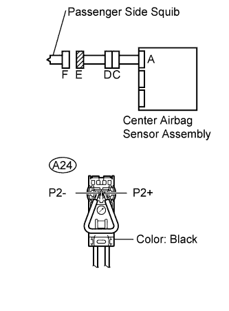
Using a service wire, connect A24-1 (P2+) and A24-2 (P2-) of connector E.
- NOTICE:
- Twist the end of the service wire in order to insert it into the connector.
- Do not forcibly insert the twisted service wire into the terminals of the connector when connecting.
Connect the negative (-) terminal cable to the battery, and wait for at least 2 seconds.
Turn the ignition switch to the ON position, and wait for at least 60 seconds.
Clear any DTCs stored in the memory (Click here).
Turn the ignition switch to the LOCK position.
Turn the ignition switch to the ON position, and wait for at least 60 seconds.
Check for DTCs (Click here).
- OK:
- DTCs B1816, B1817 and B1818 are not output.
- HINT:
- DTCs other than B1816, B1817 or B1818 may be output at this time, but they are not related to this check.
|
| ||||
| OK | |
| 20.CHECK FRONT PASSENGER AIRBAG ASSEMBLY (PASSENGER SIDE SQUIB) |
 |
- HINT:
- If continuing from step 19, begin from (c) .If continuing from any other step, being from (a).
Turn the ignition switch to the LOCK position.
Disconnect the negative (-) terminal cable from the battery, and wait for at least 90 seconds.
Disconnect the SST from connector C.
Connect the connectors to the front passenger airbag assembly.
Connect the negative (-) terminal cable to the battery, and wait for at least 2 seconds.
Turn the ignition switch to the ON position, and wait for at least 60 seconds.
Clear any DTCs stored in the memory (Click here).
Turn the ignition switch to the LOCK position.
Turn the ignition switch to the ON position, and wait for at least 60 seconds.
Check for DTCs (Click here).
- OK:
- DTC B1815, B1816, B1817 and B1818 are not output.
- HINT:
- DTCs other than B1815, B1816, B1817 or B1818 may be output at this time, but they are not related to this check.
|
| ||||
| OK | ||
| ||
| 21.CHECK CONNECTOR |
Turn the ignition switch to the LOCK position.
Disconnect the negative (-) terminal cable from the battery, and wait for at least 90 seconds
Check that the instrument panel wire assembly connectors (on the front passenger airbag assembly side) are not damaged.
- OK:
- The lock button is not disengaged, and the claw of the lock is not deformed or damaged.
|
| ||||
| OK | |
| 22.CHECK CONNECTION OF CONNECTORS |
Check that the connectors are properly connected to the center airbag sensor assembly and the instrument panel wire assembly.
- OK:
- The connectors are properly connected.
|
| ||||
| OK | |
| 23.CHECK INSTRUMENT PANEL WIRE ASSEMBLY |
Disconnect the instrument panel wire assembly connector from the instrument panel wire and front passenger airbag assembly.
|
Connect the negative (-) terminal cable to the battery, and wait for at least 2 seconds.
Turn the ignition switch to the ON position.
Measure the voltage.
- Standard voltage:
Tester Connection Condition Specified Condition A24-1 (P2+) - Body ground Ignition switch ON Below 1 V A24-2 (P2-) - Body ground Ignition switch ON Below 1 V
Turn the ignition switch to the LOCK position.
Disconnect the negative (-) terminal cable from the battery, and wait for at least 90 seconds.
Measure the resistance.
- Standard resistance:
Tester Connection Condition Specified Condition A24-1 (P2+) - A24-2 (P2-) Always Below 1 Ω A24-1 (P2+) - Body ground Always 1 MΩ or Higher A24-2 (P2-) - Body ground Always 1 MΩ or Higher
Release the activation prevention mechanism built into connector D (Click here).
Measure the resistance.
- Standard resistance:
Tester Connection Condition Specified Condition A24-1 (P2+) - A24-2 (P2-) Always 1 MΩ or Higher
|
| ||||
| OK | |
| 24.CHECK INSTRUMENT PANEL WIRE |
Restore the released activation prevention mechanism of connector B to the original condition.
|
Disconnect the instrument panel wire connector from the center airbag sensor assembly.
Connect the negative (-) terminal cable to the battery, and wait for at least 2 seconds.
Turn the ignition switch to the ON position.
Measure the voltage.
- Standard voltage:
Tester Connection Condition Specified Condition IG1-1 (P2+) - Body ground Ignition switch ON Below 1 V IG1-2 (P2-) - Body ground Ignition switch ON Below 1 V
Turn the ignition switch to the LOCK position.
Disconnect the negative (-) terminal cable from the battery, and wait for at least 90 seconds.
Measure the resistance.
- Standard resistance:
Tester Connection Condition Specified Condition IG1-1 (P2+) - IG1-2 (P2-) Always Below 1 Ω IG1-1 (P2+) - Body ground Always 1 MΩ or Higher IG1-2 (P2-) - Body ground Always 1 MΩ or Higher
Release the activation prevention mechanism built into connector B (Click here).
Measure the resistance.
- Standard resistance:
Tester Connection Condition Specified Condition IG1-1 (P2+) - IG1-2 (P2-) Always 1 MΩ or Higher
|
| ||||
| OK | |
| 25.CHECK CENTER AIRBAG SENSOR ASSEMBLY |
Replace the front passenger airbag (Click here).
 |
- HINT:
- Perform the inspection using parts from a normal vehicle when possible.
Connect the instrument panel wire to the center airbag sensor assembly and spiral cable.
Connect the connectors to the center airbag sensor assembly.
Connect the negative (-) terminal cable to the battery, and wait for at least 2 seconds.
Turn the ignition switch to the ON position, and wait for at least 60 seconds.
Clear any DTCs stored in the memory (Click here).
Turn the ignition switch to the LOCK position.
Turn the ignition switch to the ON position, and wait for at least 60 seconds.
Check for DTCs (Click here).
- OK:
- DTC 54 is not output.
- HINT:
- DTCs other than 54 may be output at this time, but they are not related to this check.
|
| ||||
| OK | ||
| ||