ENGINE IMMOBILISER SYSTEM > TERMINALS OF ECU |

for Preparation Click here
| CHECK TRANSPONDER KEY AMPLIFIER |

Disconnect the T9 amplifier connector.
Measure the resistance according to the value(s) in the table below.
Terminal No. (Symbol) Wiring Color Terminal Description Condition Specified Condition T9-7 (AGND) - Body ground L - Body ground Ground Always Below 1 Ω - If the result is not as specified, there may be a malfunction on the wire harness side.
- If the result is not as specified, there may be a malfunction on the wire harness side.
Reconnect the T9 amplifier connector.
Measure the resistance and voltage according to the value(s) in the table below.
Terminal No. (Symbol) Wiring Color Terminal Description Condition Specified Condition T9-1 (VC5) - T9-7 (AGND) GR-B - L Power source No key in ignition key cylinder Below 1 V T9-1 (VC5) - T9-7 (AGND) GR-B - L Power source Key inserted 4.6 to 5.4 V T9-4 (CODE) - T9-7 (AGND) P-G - L Demodulated signal of key code data No key in ignition key cylinder →
Key insertedPulse generation
(see waveform 1)T9-5 (TXCT) - T9-7 (AGND) LG-R - L Key code output signal No key in ignition key cylinder →
Key insertedPulse generation
(see waveform 2)T9-7 (AGND) - Body ground L - Body ground Ground Always Below 1 Ω - If the result is not as specified, there may be a malfunction on the amplifier.
- If the result is not as specified, there may be a malfunction on the amplifier.
Inspect using an oscilloscope.
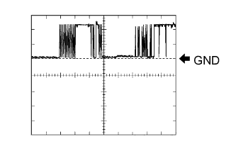
Waveform 1
Tester Connection T9-4 (CODE) - T9-7 (AGND) Tool Setting 2 V/DIV., 20 msec/DIV. Condition No key in ignition key cylinder → Key inserted Waveform 2
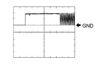
Tester Connection T9-5 (TXCT) - T9-7 (AGND) Tool Setting 2 V/DIV., 20 msec/DIV. Condition No key in ignition key cylinder → Key inserted

| CHECK TRANSPONDER KEY ECU ASSEMBLY |
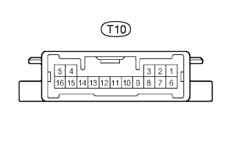
Disconnect the T10 ECU connector.
Measure the resistance and voltage according to the value(s) in the table below.
If the result is not as specified, there may be a malfunction on the wire harness side.Terminal No. (Symbol) Wiring Color Terminal Description Condition Specified Condition T10-16 (GND) - Body ground W-B - Body ground Ground Always Below 1 Ω T10-1 (+B) - T10-16 (GND) R - W-B Battery Always 11 to 14 V T10-2 (IG) - T10-16 (GND) BE - W-B Ignition switch Ignition switch OFF Below 1 V T10-2 (IG) - T10-16 (GND) BE - W-B Ignition switch Ignition switch ON 11 to 14 V T10-3 (KSW) - T10-5 (AGND) G-B - L Unlock warning switch No key in ignition key cylinder 10 kΩ or higher T10-3 (KSW) - T10-5 (AGND) G-B - L Unlock warning switch Key inserted Below 1Ω Reconnect the T10 ECU connector.
Measure the voltage according to the value(s) in the table below.
If the result is not as specified, there may be a malfunction on the ECU.Terminal No. (Symbol) Wiring Color Terminal Description Condition Specified Condition T10-14 (VC5) - T10-16 (GND) GR-B - W-B Power source No key in ignition key cylinder 0 V T10-14 (VC5) - T10-16 (GND) GR-B - W-B Power source Key inserted 4.6 to 5.4 V T10-4 (TXCT) - T10-16 (GND) LG-R - W-B Transponder key amplifier communication signal No key in ignition key cylinder →
Key insertedPulse generation
(see waveform 1)T10-15 (CODE) - T10-16 (GND) P-G - W-B Transponder key amplifier communication signal No key in ignition key cylinder →
Key insertedPulse generation
(see waveform 2)T10-13 (EFIO) - T10-16 (GND) L-W - W-B ECM output signal Ignition switch OFF → ON Pulse generation
(see waveform 3)T10-12 (EFII) - T10-16 (GND) LG-B - W-B ECM input signal Ignition switch off 11 to 14 V Within 3 seconds after starter operates and initial combustion occurs, or within 3seconds after ignition switch first turned on (IG) after battery disconnected and connected. Pulse generation
(see waveform 4)Inspect using an oscilloscope.
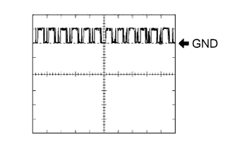
Waveform 1
Tester Connection T10-4 (TXCT) - T10-16 (GND) Tool Setting 2.5 V/DIV., 20 msec/DIV. Condition No key in ignition key cylinder → Key inserted Waveform 2
Tester Connection T10-15 (CODE) - T10-16 (GND) Tool Setting 2.5 V/DIV., 20 msec/DIV. Condition No key in ignition key cylinder → Key inserted Waveform 3
Tester Connection T10-13 (EFIO) - T10-16 (GND) Tool Setting 12 V/DIV., 100 msec/DIV. Condition Ignition switch OFF → ON Waveform 4
Tester Connection T10-12 (EFII) - T10-16 (GND) Tool Setting 5 V/DIV., 500 ms/DIV. Condition Within 3 seconds after starter operates and initial combustion occurs, or within 3seconds after ignition switch first turned on (IG) after battery disconnected and connected.

| CHECK ECM (for 2TR-FE) |

Disconnect the E4 ECM connectors.
Measure the resistance according to the value(s) in the table below.
Terminal No. (Symbol) Wiring Color Terminal Description Condition Specified Condition E4-3 (E1) - Body ground BR - Body ground Ground Always Below 1 Ω - If the result is not as specified, there may be a malfunction on the wire harness side.
- If the result is not as specified, there may be a malfunction on the wire harness side.
Reconnect the E4 ECM connectors.
Measure the voltage according to the value(s) in the table below.
Terminal No. (Symbol) Wiring Color Terminal Description Condition Specified Condition E7-16 (IMI) - E4-3 (E1) L-W - BR Transponder key ECU input signal Ignition switch off Below 1 V Ignition switch on Pulse generation
(see waveform 1)E7-15 (IMO) - E4-3 (E1) LG-B - BR Transponder key ECU output signal Ignition switch off 11 to 14 V Within 3 seconds after starter operates and initial combustion occurs, or within 3seconds after ignition switch first turned on (IG) after battery disconnected and connected. Pulse generation
(see waveform 2)- If the result is not as specified, the ECM may have a malfunction.
- If the result is not as specified, the ECM may have a malfunction.
Inspect using an oscilloscope.
Waveform 1
Tester Connection E7-16 (IMI) - E4-3 (E1) Tool Setting 10 V/DIV., 100 msec/DIV. Condition Ignition switch on Waveform 2
Tester Connection E7-15 (IMO) - E4-3 (E1) Tool Setting 5 V/DIV., 500 msec/DIV. Condition Within 3 seconds after starter operates and initial combustion occurs, or within 3seconds after ignition switch first turned on (IG) after battery disconnected and connected.
| CHECK ECM (for 1GR-FE) |
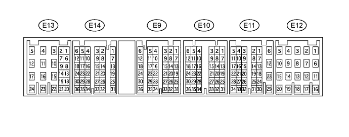
Disconnect the E11 ECM connectors.
Measure the resistance according to the value(s) in the table below.
Terminal No. (Symbol) Wiring Color Terminal Description Condition Specified Condition E11-12 (E1) - Body ground BR - Body ground Ground Always Below 1 Ω - If the result is not as specified, there may be a malfunction on the wire harness side.
- If the result is not as specified, there may be a malfunction on the wire harness side.
Disconnect the E11 ECM connectors.
Measure the voltage according to the value(s) in the table below.
Terminal No. (Symbol) Wiring Color Terminal Description Condition Specified Condition E14-14 (IMI) - E11-12 (E1) L-W - BR Transponder key ECU input signal Ignition switch off Below 1 V Ignition switch on Pulse generation
(see waveform 1)E14-20 (IMO) - E11-12 (E1) LG-B - BR Transponder key ECU output signal Ignition switch off 11 to 14 V Within 3 seconds after starter operates and initial combustion occurs, or within 3seconds after ignition switch first turned on (IG) after battery disconnected and connected. Pulse generation
(see waveform 2)- If the result is not as specified, the ECM may have a malfunction.
- If the result is not as specified, the ECM may have a malfunction.
Inspect using an oscilloscope.
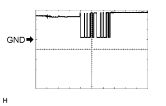
Waveform 1
Tester Connection E14-14 (IMI) - E11-12 (E1) Tool Setting 10 V/DIV., 100 msec/DIV. Condition Ignition switch on Waveform 2
Tester Connection E14-20 (IMO) - E11-12 (E1) Tool Setting 5 V/DIV., 500 msec/DIV. Condition Within 3 seconds after starter operates and initial combustion occurs, or within 3seconds after ignition switch first turned on (IG) after battery disconnected and connected.