REAR VIEW MONITOR SYSTEM (w/ Navigation System) > Display Signal Circuit between Navigation Receiver Assembly and Television Camera Assembly |

for Preparation Click here
DESCRIPTION
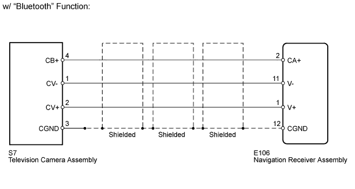
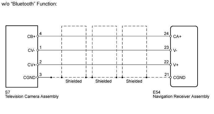
This is the display signal circuit of the television camera.WIRING DIAGRAM
INSPECTION PROCEDURE
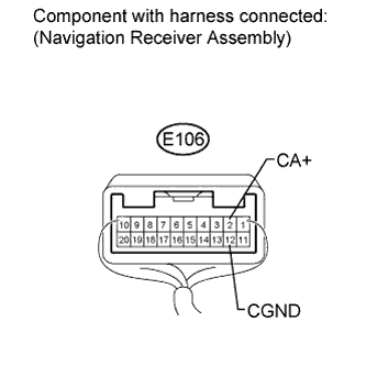
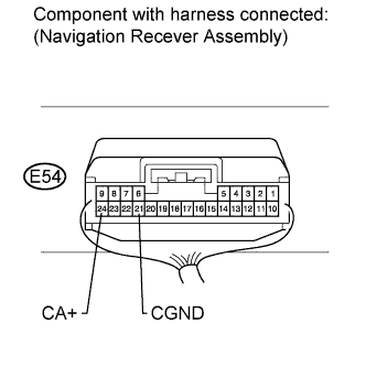
| 1.CHECK NAVIGATION RECEIVER ASSEMBLY |
w/ "Bluetooth" Function:
Measure the voltage according to the value(s) in the table below.
- Standard Voltage:
Tester Connection Switch Condition Specified Condition E106-2 (CA+) - E106-12 (CGND) Ignition switch ON, shift lever in R 5.5 to 7.05 V
 |
w/o "Bluetooth" Function:
Measure the voltage according to the value(s) in the table below.
- Standard Voltage:
Tester Connection Switch Condition Specified Condition E54-24 (CA+) - E54-21 (CGND) Ignition switch ON, shift lever in R 5.5 to 7.05 V
 |
| Result | Proceed to |
| OK | A |
| NG (for HDD Navigation System) | B |
| NG (for DVD Navigation System) | C |
|
| ||||
|
| ||||
| A | |
| 2.CHECK TELEVISION CAMERA ASSEMBLY |
w/ "Bluetooth" Function:
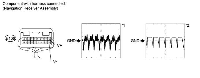
Using an oscilloscope, check the waveform.
Measurement Condition Item Content Tester Connection E106-1 (V+) - E106-11 (V-) Tool Setting 0.2 V/DIV., 50 μs/DIV. Condition - Ignition switch ON, shift lever in R*1
- Ignition switch ON, shift lever in R, screen blacked out by covering camera lens*2
- OK:
- Waveform is as shown in illustration.
- Ignition switch ON, shift lever in R*1
w/o "Bluetooth" Function:
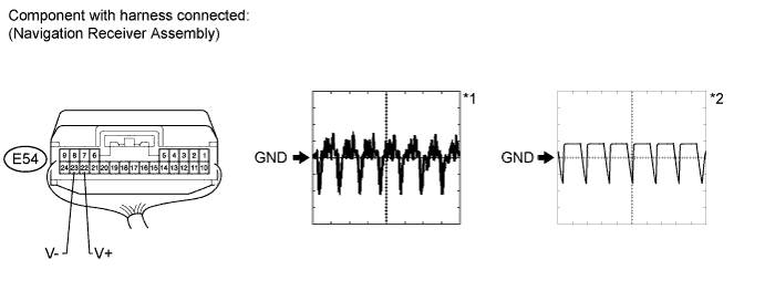
Using an oscilloscope, check the waveform.
Measurement Condition Item Content Tester Connection E54-23 (V-) - E54-22 (V+) Tool Setting 0.2 V/DIV., 50 μs/DIV. Condition - Ignition switch ON, shift lever in R*1
- Ignition switch ON, shift lever in R, screen blacked out by covering camera lens*2
- OK:
- Waveform is as shown in illustration.
- Ignition switch ON, shift lever in R*1
|
| ||||
| OK | ||
| ||
| 3.CHECK HARNESS AND CONNECTOR (NAVIGATION RECEIVER ASSEMBLY - TELEVISION CAMERA ASSEMBLY) |
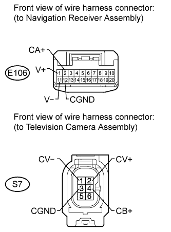
w/ "Bluetooth" Function:
Disconnect the E106 navigation receiver assembly connector.
Disconnect the S7 television camera assembly connector.
Measure the resistance according to the value(s) in the table below.
- Standard Resistance:
Tester Connection Condition Specified Condition E106-2 (CA+) - S7-4 (CB+) Always Below 1 Ω E106-12 (CGND) - S7-3 (CGND) Always Below 1 Ω E106-1 (V+) - S7-2 (CV+) Always Below 1 Ω E106-11 (V-) - S7-1 (CV-) Always Below 1 Ω E106-2 (CA+) - Body ground Always 10 kΩ or higher E106-12 (CGND) - Body ground Always 10 kΩ or higher E106-1 (V+) - Body ground Always 10 kΩ or higher E106-11 (V-) - Body ground Always 10 kΩ or higher
 |
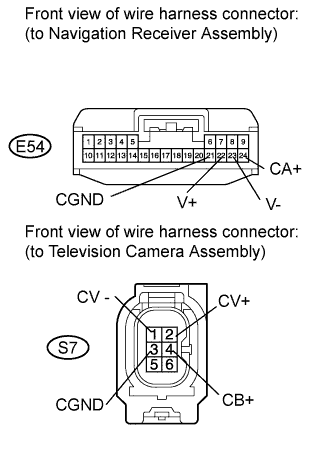
w/ "Bluetooth" Function:
Disconnect the E54 navigation receiver assembly connector.
Disconnect the S7 television camera assembly connector.
Measure the resistance according to the value(s) in the table below.
- Standard Resistance:
Tester Connection Condition Specified Condition E54-24 (CA+) - S7-4 (CB+) Always Below 1 Ω E54-21 (CGND) - S7-3 (CGND) Always Below 1 Ω E54-22 (V+) - S7-2 (CV+) Always Below 1 Ω E54-23 (V-) - S7-1 (CV-) Always Below 1 Ω E54-24 (CA+) - Body ground Always 10 kΩ or higher E54-21 (CGND) - Body ground Always 10 kΩ or higher E54-22 (V+) - Body ground Always 10 kΩ or higher E54-23 (V-) - Body ground Always 10 kΩ or higher
 |
|
| ||||
| OK | ||
| ||