REAR DRIVE SHAFT ASSEMBLY > DISASSEMBLY |

for Preparation Click here
- HINT:
- Use the same procedures for the RH side and LH side.
- The procedures listed below are for the LH side.
| 1. REMOVE REAR DRIVE SHAFT INBOARD JOINT BOOT NO. 2 CLAMP LH |
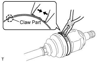 |
Using needle-nose pliers, remove the No. 2 inboard joint boot clamp, as shown in the illustration.
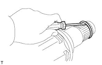
| 2. REMOVE REAR DRIVE SHAFT INBOARD JOINT BOOT CLAMP LH |
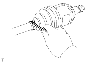 |
Using a screwdriver, remove the inboard joint boot clamp, as shown in the illustration.
| 3. REMOVE REAR AXLE INBOARD JOINT BOOT |
Remove the boot from the inboard joint.
| 4. REMOVE REAR DRIVE SHAFT INBOARD JOINT ASSEMBLY LH |
 |
Remove any old grease from the inboard joint.
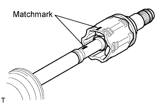
Put matchmarks on the inboard joint and outboard joint shaft.
- NOTICE:
- Do not punch the marks.
Remove the inboard joint from the outboard joint shaft.
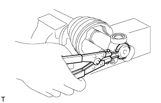
Using a snap ring expander, remove the shaft snap ring.
 |
Put matchmarks on the outboard joint shaft and tripod joint.
- NOTICE:
- Do not punch the marks.
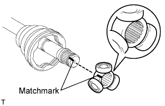 |
Using a brass bar and hammer, tap out the tripod joint from the outboard joint shaft.
- NOTICE:
- Do not tap the rollers.
Remove the inboard joint boot.
| 5. REMOVE REAR DRIVE SHAFT INBOARD JOINT LH SHAFT SNAP RING |
 |
Using a screwdriver, remove the hole snap ring.
| 6. REMOVE REAR DRIVE SHAFT DUST COVER LH |
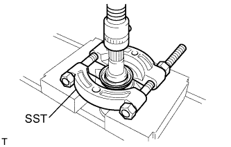 |
Using SST and a press, press out the shaft dust cover.
- SST
- 09950-00020
- NOTICE:
- Be careful not to drop the inboard joint.