LIGHTING SYSTEM > Automatic Light Control Sensor Circuit |

for Preparation Click here
DESCRIPTION
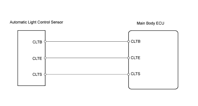
The main body ECU receives the signal from the automatic light control sensor.WIRING DIAGRAM
INSPECTION PROCEDURE
| 1.CHECK WIRE HARNESS (MAIN BODY ECU - AUTOMATIC LIGHT CONTROL SENSOR) |
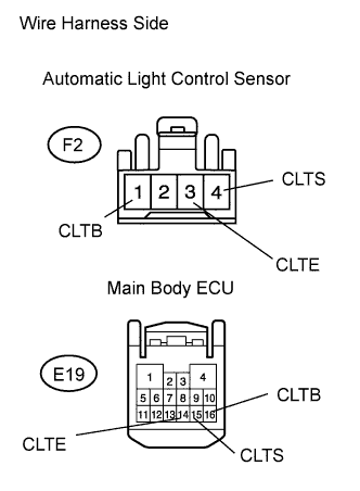 |
Disconnect the E19 main body ECU connector.
Disconnect the F2 automatic light control sensor connector.
Measure the resistance of the wire harness side connectors.
- Standard resistance:
Tester Connection Specified Condition E19-14 (CLTE) - F2-3 (CLTE) Below 1 Ω E19-14 (CLTE) or F2-3 (CLTE) - Body ground 10 kΩ or higher E19-15 (CLTS) - F2-4 (CLTS) Below 1 Ω E19-15 (CLTS) or F2-4 (CLTS) - Body ground 10 kΩ or higher E19-16 (CLTB) - F2-1 (CLTB) Below 1 Ω E19-16 (CLTB) or F2-1 (CLTB) - Body ground 10 kΩ or higher
|
| ||||
| OK | |
| 2.CHECK OPERATION OF AUTOMATIC LIGHT CONTROL SENSOR |
Replace the automatic light control sensor with a normally functioning one or a new one.
Check for DTC.
- OK:
- DTC is not output.
|
| ||||
| OK | ||
| ||