AIR CONDITIONING UNIT > INSTALLATION |

for Preparation Click here
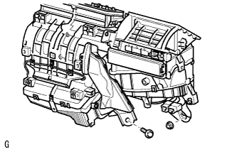
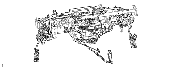
| 1. INSTALL AIR CONDITIONING UNIT ASSEMBLY |
Install the air conditioning unit with the bolt and nut.
- Torque:
- 9.8 N*m{ 100 kgf*cm , 7 ft.*lbf }
 |
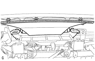
| 2. INSTALL INSTRUMENT PANEL REINFORCEMENT |
Install the instrument panel reinforcement with the 6 bolts.
- Torque:
- 20 N*m{ 204 kgf*cm , 15 ft.*lbf }
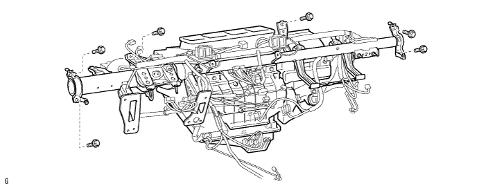
Install the 3 bolts.
- Torque:
- 9.8 N*m{ 100 kgf*cm , 7 ft.*lbf }
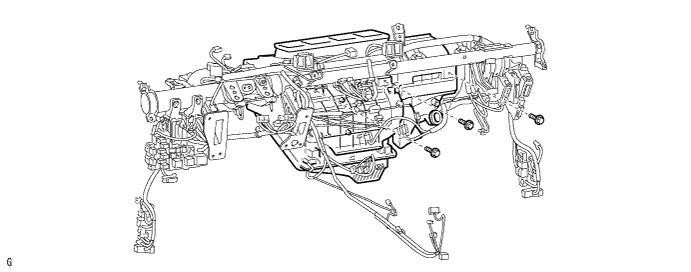
Install the 4 bolts and connect the ground wire.
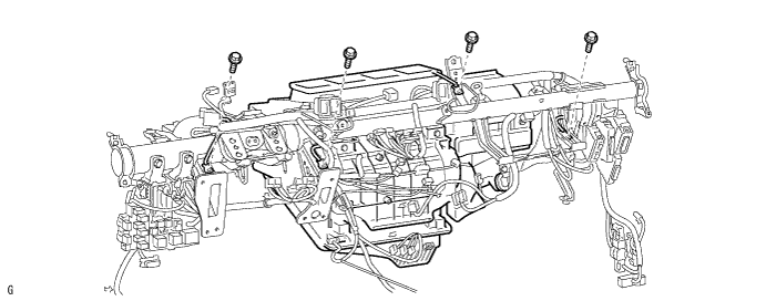
Attach the 12 clamps.
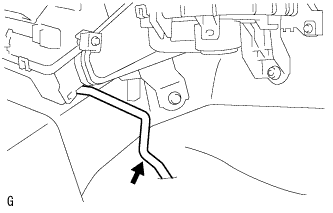
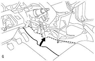
| 3. INSTALL DRAIN COOLER HOSE |
Install the drain hose.
 |
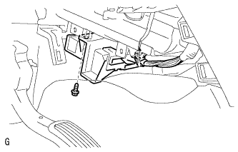
| 4. INSTALL AIR CONDITIONING AMPLIFIER ASSEMBLY |
Install the air conditioning amplifier with the screw.
 |
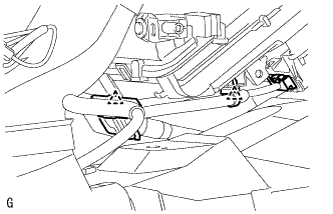
Connect the connector.
Attach the 2 clamps to the amplifier.
 |
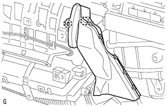
| 5. INSTALL AIR DUCT |
Attach the 2 claws to install the air duct.
 |
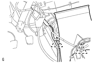
| 6. INSTALL REAR AIR DUCT |
Attach the 3 claws to install the air duct rear.
 |
Attach the 2 clamps to install the wire harness.
 |
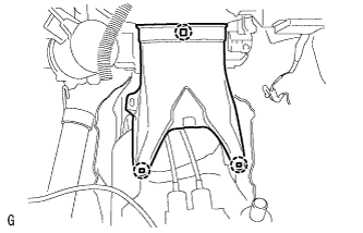
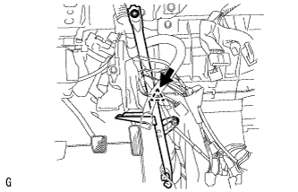
| 7. INSTALL NO. 1 INSTRUMENT PANEL BRACE SUB-ASSEMBLY |
Install the instrument panel brace with the bolt, nut and screw.
 |
Install the clamp and connect the wire harness.
 |
Reposition the floor carpet.
 |
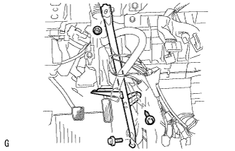
| 8. INSTALL DEFROSTER NOZZLE ASSEMBLY |
Attach the 3 claws to install the defroster nozzle assembly lower.
 |
| 9. INSTALL LOWER INSTRUMENT PANEL |
Install the lower instrument panel (Click here).
| 10. INSTALL UPPER INSTRUMENT PANEL |
Install the upper instrument panel (Click here).
| 11. INSTALL STEERING COLUMN ASSEMBLY |
Install the steering column (Click here).
| 12. CONNECT HEATER WATER OUTLET HOSE |
Connect the water hose and attach the clip.
 |
| 13. CONNECT HEATER WATER INLET HOSE |
- HINT:
- Use the same procedures described for the water outlet hose.
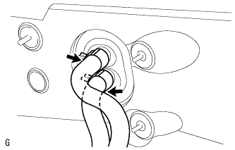
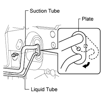
| 14. CONNECT TUBE SUB-ASSEMBLY |
Remove the attached vinyl tape from the pipe.
 |
Sufficiently apply compressor oil to new 2 O-rings and the fitting surface of the suction tube and liquid tube.
- Compressor oil:
- ND-OIL 8 or equivalent
Install the 2 O-rings on the suction tube and liquid tube.
Connect the suction tube and liquid tube.
- HINT:
- After the connection, check that the claw of the piping clamp is engaged.
Install the plate with the bolt.
- Torque:
- 9.8 N*m{ 100 kgf*cm , 7 ft.*lbf }
| 15. CONNECT CABLE TO NEGATIVE BATTERY TERMINAL |
| 16. CHECK SRS WARNING LIGHT |
Check the SRS warning light (Click here).
| 17. ADD ENGINE COOLANT |
For 2AD-FTV, refer to the following procedures (Click here).
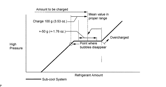
| 18. CHARGE REFRIGERANT |
Perform vacuum purging using a vacuum pump.
Charge refrigerant HFC-134a (R134a).
- Standard:
- 430 +-30 g (15.2 +-1.1 oz.)
- SST
- 09985-20010
(09985-02130, 09985-02150, 09985-02090, 09985-02110, 09985-02010, 09985-02050, 09985-02060, 09985-02070)
- NOTICE:
- Do not operate the cooler compressor before charging refrigerant as the cooler compressor will not work properly without any refrigerant, and will overheat.
- Approximately 100 g (3.53 oz.) of refrigerant may need to be charged after bubbles disappear. The refrigerant amount should be checked by measuring its quantity, and not with the sight glass.
| 19. WARM UP ENGINE |
Warm up the engine at less than 1,850 rpm for 2 minutes or more after charging the refrigerant.
- NOTICE:
- Be sure to warm up the compressor when turning the A/C switch ON after removing and installing the cooler refrigerant lines (including the compressor), to prevent damage to the compressor.
| 20. CHECK FOR ENGINE COOLANT LEAKS |
For 2AD-FTV: (Click here)
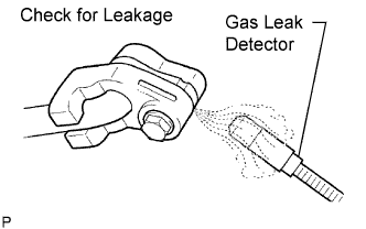
| 21. CHECK FOR LEAKAGE OF REFRIGERANT |
After recharging the refrigerant gas, check for refrigerant gas leakage using a halogen leak detector.
Perform the operation under these conditions:
- Stop the engine.
- Secure good ventilation (the gas leak detector may react to volatile gases other than refrigerant, such as evaporated gasoline or exhaust gas).
- Repeat the test 2 or 3 times.
- Make sure that some refrigerant remains in the refrigeration system. When compressor is off: approximately 392 to 588 kPa (4 to 6 kgf/cm2, 57 to 85 psi)
- Stop the engine.
Using a gas leak detector, check the refrigerant line for leakage.
 |
If a gas leak is not detected on the drain hose, remove the blower motor control (blower resistor) from the cooling unit. Insert the gas leak detector sensor into the unit and perform the test.
Disconnect the connector and leave the pressure switch on for approximately 20 minutes. Bring the gas leak detector close to the pressure switch and perform the test.