OUTPUT SHAFT > REASSEMBLY |

for Preparation Click here
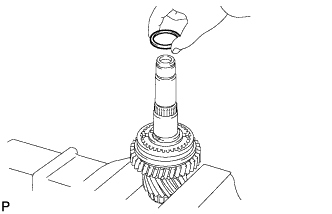
| 1. INSTALL NEEDLE ROLLER BEARING |
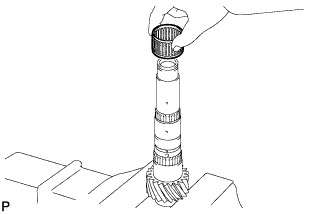
Coat the needle roller bearing with gear oil, and install it into the No. 2 output shaft.
 |
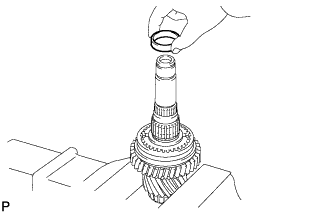
| 2. INSTALL REVERSE DRIVEN GEAR |
Coat the reverse driven gear with gear oil, and install it into the No. 2 output shaft.
 |
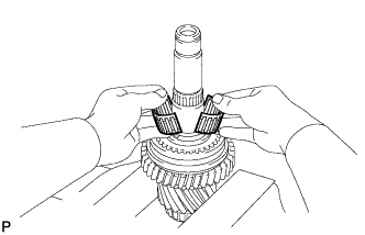
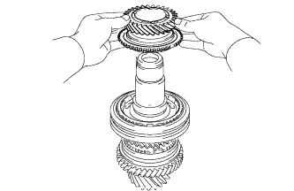
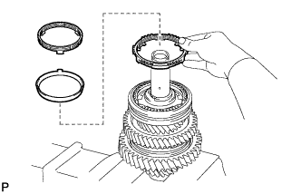
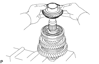
| 3. INSTALL NO. 4 TRANSMISSION CLUTCH HUB |
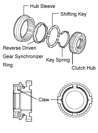
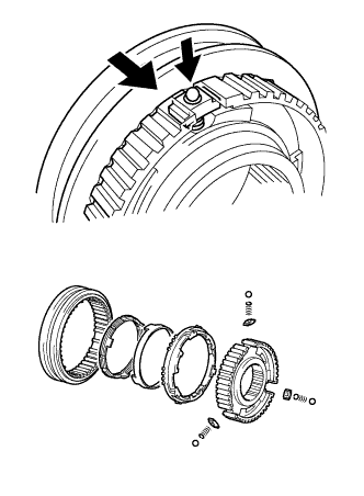
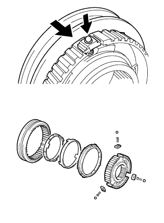
Install the key spring and 2 shifting keys to the clutch hub.
- HINT:
- Install the shifting key with the grooves on the clutch hub side.
- Install the key spring with the claw on the clutch hub side.
- Refer to the illustration when installing the key spring and shifting keys.
 |
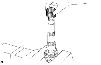
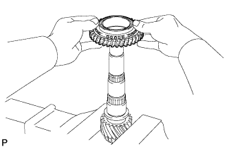
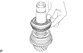
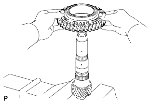
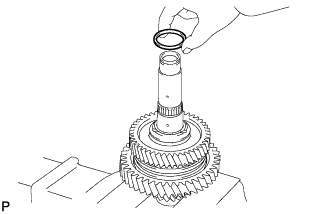
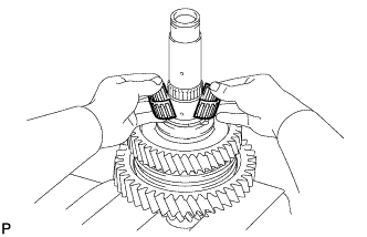
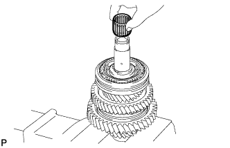
Install the hub sleeve to the reverse driven gear as shown in the illustration.
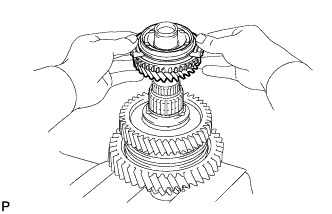
Coat the No. 4 transmission clutch hub with gear oil, and install it into the No. 2 output shaft.
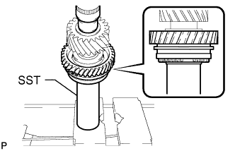 |
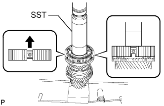
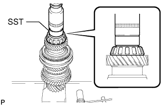
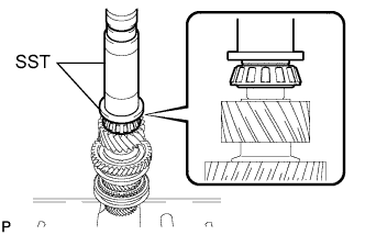
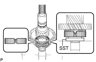
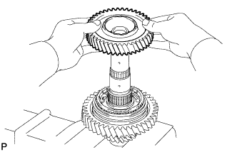
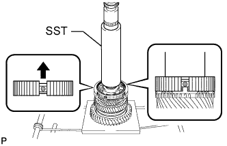
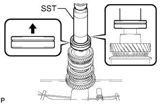
Using SST and a press, install the reverse gear and No. 4 transmission clutch hub into the No. 2 output shaft.
- SST
- 09308-14010
- NOTICE:
- After installation, make sure that the gear and synchronizer ring move smoothly.
- HINT:
- Make sure that the protruding part on the synchronizer ring is fitted into the groove of the clutch hub.
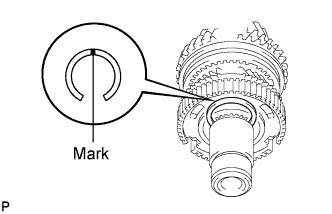
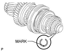
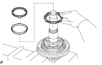
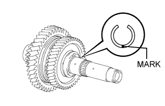
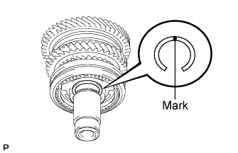
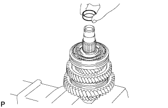
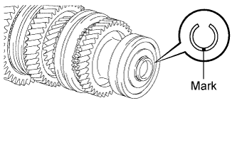
| 4. INSTALL SHAFT SNAP RING |
Using the table below, select a new snap ring that makes the thrust clearance of the No. 4 transmission clutch hub less than 0.1 mm (0.004 in.).
- Standard snap ring thickness:
Mark Thickness Mark Thickness A 2.25 to 2.30 mm (0.0886 to 0.0906 in.) E 2.45 to 2.50 mm (0.0965 to 0.0984 in.) B 2.30 to 2.35 mm (0.0906 to 0.0925 in.) F 2.50 to 2.55 mm (0.0984 to 0.1004 in.) C 2.35 to 2.40 mm (0.0925 to 0.0945 in.) G 2.55 to 2.60 mm (0.1004 to 0.1024 in.) D 2.40 to 2.45 mm (0.0945 to 0.0965 in.) H 2.60 to 2.65 mm (0.1024 to 0.1043 in.)
 |
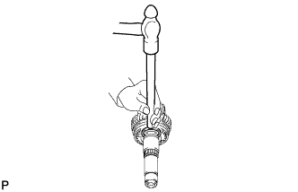
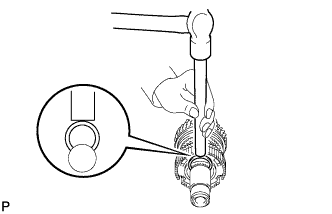
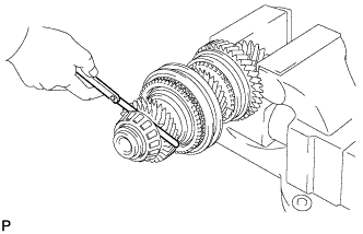
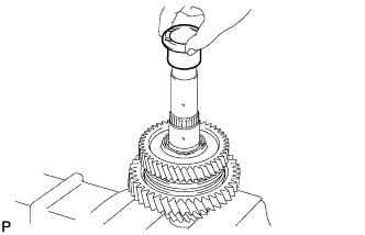
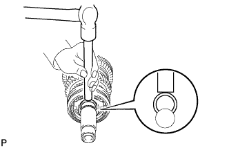
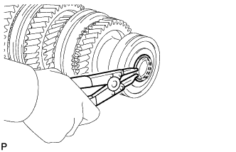
Using a brass bar and hammer, tap the snap ring onto the No. 2 output shaft.
 |
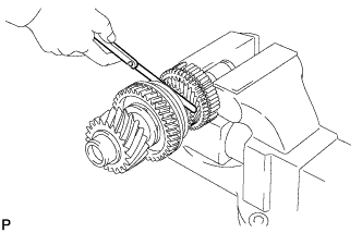
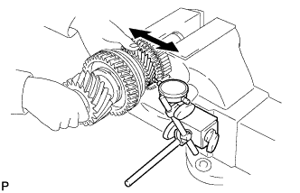
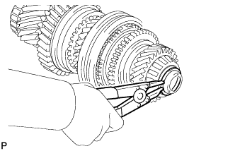
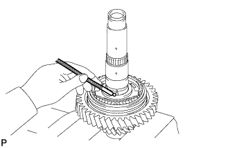
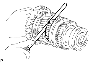
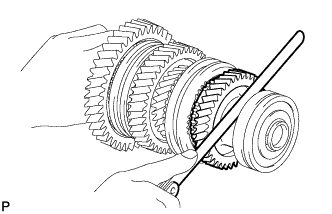
| 5. INSPECT REVERSE DRIVEN GEAR THRUST CLEARANCE |
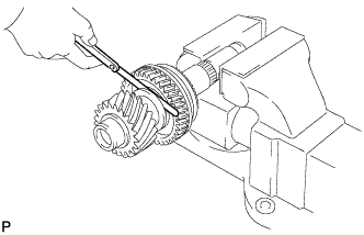
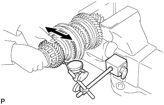
Using a feeler gauge, measure the thrust clearance.
- Standard thrust clearance:
- 0.11 to 0.34 mm (0.0043 to 0.0134 in.)
- Maximum thrust clearance:
- 0.34 mm (0.0134 in.)
 |
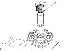
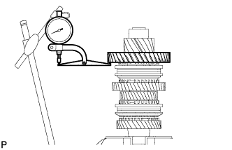
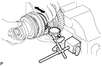
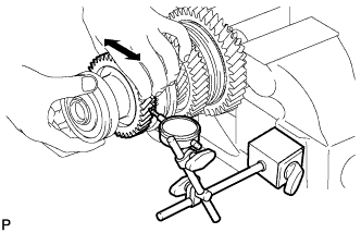
| 6. INSPECT REVERSE DRIVEN GEAR RADIAL CLEARANCE |
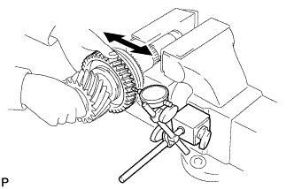
Using a dial indicator, measure the radial clearance.
- Standard radial clearance:
- 0.015 to 0.068 mm (0.0006 to 0.0027 in.)
- Maximum radial clearance:
- 0.068 mm (0.0027 in.)
 |
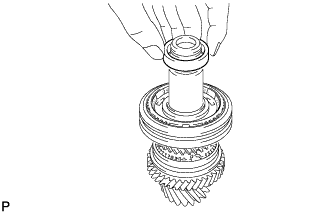
| 7. INSTALL 5TH DRIVEN GEAR |
Install the output shaft spacer into the No. 2 output shaft.
 |
Coat the needle roller bearing with gear oil, and install it into the No. 2 output shaft.
 |
Install the output shaft spacer into the No. 2 output shaft.
 |
Coat the 5th driven gear with gear oil, and install it into the No. 2 output shaft.
 |
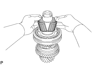
| 8. INSTALL NO. 3 TRANSMISSION CLUTCH HUB |
Apply gear oil to the sleeve and hub.
 |
Install the clutch hub sleeve to the clutch hub.
Install the 3 shifting keys to the clutch hub.
Install the 3 shifting key springs to the clutch hub.
Place the balls in the holes of the shifting keys, and install the hub sleeve while pushing in the balls.
- NOTICE:
- Take care to prevent the balls from scattering.
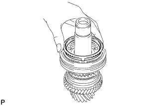
Coat the 5th driven gear synchronizer ring set with gear oil, and install them to the 5th driven gear.
 |
Using SST and a press, press in the No. 3 transmission clutch hub to the No. 2 output shaft.
- SST
- 09308-14010
- NOTICE:
- After installation, make sure that the gear and synchronizer ring move smoothly.
- HINT:
- Make sure that the protruding part on the synchronizer ring is fitted into the groove of the clutch hub.
| 9. INSTALL SHAFT SNAP RING |
Using the table below, select a new snap ring that makes the thrust clearance of the No. 3 transmission clutch hub less than 0.1 mm (0.004 in.).
- Standard snap ring thickness:
Mark Thickness Mark Thickness 1 2.25 to 2.30 mm (0.0886 to 0.0906 in.) 4 2.40 to 2.45 mm (0.0945 to 0.0965 in.) 2 2.30 to 2.35 mm (0.0906 to 0.0925 in.) 5 2.45 to 2.50 mm (0.0965 to 0.0984 in.) 3 2.35 to 2.40 mm (0.0925 to 0.0945 in.) 6 2.50 to 2.55 mm (0.0984 to 0.1004 in.)
 |
Using a brass bar and hammer, tap the snap ring onto the No. 2 output shaft.
 |
| 10. INSPECT 5TH DRIVEN GEAR THRUST CLEARANCE |
Using a feeler gauge, measure the thrust clearance.
- Standard thrust clearance:
- 0.10 to 0.55 mm (0.0039 to 0.0217 in.)
- Maximum thrust clearance:
- 0.55 mm (0.0217 in.)
 |
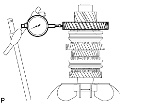
| 11. INSPECT 5TH DRIVEN GEAR RADIAL CLEARANCE |
Using a dial indicator, measure the radial clearance.
- Standard radial clearance:
- 0.015 to 0.066 mm (0.0006 to 0.0026 in.)
- Maximum radial clearance:
- 0.066 mm (0.0026 in.)
 |
| 12. INSTALL 6TH DRIVEN GEAR |
Install the output shaft spacer into the No. 2 output shaft.
 |
Coat the needle roller bearing with gear oil, and install it into the No. 2 output shaft.
 |
Coat the synchronizer ring with gear oil, and install it into the transmission clutch hub.
 |
Coat the 6th driven gear with gear oil, and install it into the No. 2 output shaft.
 |
| 13. INSTALL NO. 2 OUTPUT SHAFT REAR BEARING |
Using SST and a press, press the No. 2 output shaft rear bearing into the No. 2 output shaft.
- SST
- 09710-04071
- NOTICE:
- After installation, make sure that the gear and synchronizer ring move smoothly.
 |
| 14. INSTALL NO. 2 OUTPUT SHAFT BEARING SNAP RING |
Using the table below, select a new snap ring that makes the thrust clearance of the 6th gear less than 0.1 mm (0.004 in.).
- Standard snap ring thickness:
Mark Thickness Mark Thickness B 1.85 to 1.90 mm (0.0728 to 0.0748 in.) 0 2.05 to 2.10 mm (0.0807 to 0.0827 in.) C 1.90 to 1.95 mm (0.0748 to 0.0768 in.) 1 2.10 to 2.15 mm (0.0827 to 0.0846 in.) D 1.95 to 2.00 mm (0.0768 to 0.0787 in.) 2 2.15 to 2.20 mm (0.0846 to 0.0866 in.) E 2.00 to 2.05 mm (0.0787 to 0.0807 in.) - -
 |
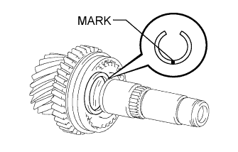
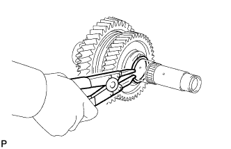
Using a snap ring expander, install the snap ring onto the No. 2 output shaft.
 |
| 15. INSPECT 6TH DRIVEN GEAR THRUST CLEARANCE |
Using a feeler gauge, measure the thrust clearance.
- Standard thrust clearance:
- 0.10 to 0.55 mm (0.0039 to 0.0217 in.)
- Maximum thrust clearance:
- 0.55 mm (0.0217 in.)
 |
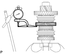
| 16. INSPECT 6TH DRIVEN GEAR RADIAL CLEARANCE |
Using a dial indicator, measure the radial clearance.
- Standard radial clearance:
- 0.015 to 0.066 mm (0.0006 to 0.0026 in.)
- Maximum radial clearance:
- 0.066 mm (0.0026 in.)
 |
| 17. INSTALL NO. 2 OUTPUT SHAFT FRONT BEARING |
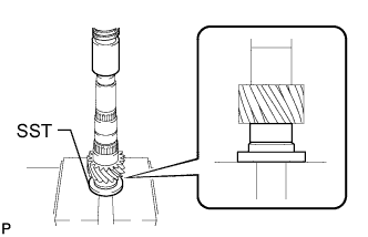
Using SST and a press, press the No. 2 output shaft front bearing into the No. 2 output shaft.
- SST
- 09309-37010
09506-30012
 |
| 18. INSTALL OUTPUT SHAFT FRONT BEARING |
Using SST and a press, press the output shaft front bearing into the No. 1 output shaft.
- SST
- 09309-14040
 |
| 19. INSTALL OUTPUT SHAFT FRONT BEARING SHAFT SNAP RING |
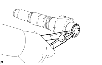
Using a snap ring expander, install a new snap ring into the No. 1 output shaft.
 |
| 20. INSTALL 1ST DRIVEN GEAR |
Coat the needle roller bearing with gear oil, and install it into the No. 1 output shaft.
 |
Coat the 1st driven gear with gear oil, and install it into the No. 1 output shaft.
 |
| 21. INSTALL NO. 1 TRANSMISSION CLUTCH HUB |
Apply gear oil to the sleeve and hub.
 |
Install the clutch hub sleeve to the clutch hub.
Install the 3 shifting keys to the clutch hub.
Install the 3 shifting key springs to the clutch hub.
Place the balls in the holes of the shifting keys, and install the hub sleeve while pushing in the balls.
- NOTICE:
- Take care to prevent the balls from scattering.
Coat the 1st driven gear synchronizer ring set with gear oil, and install them to the 1st driven gear.
 |
Using SST and a press, press in the No. 1 transmission hub sleeve to the No. 1 output shaft.
- SST
- 09726-40010
- NOTICE:
- After installation, make sure that the gear and synchronizer ring move smoothly.
- HINT:
- Make sure that the protruding part on the synchronizer ring is fitted into the groove of the clutch hub.
| 22. INSTALL 2ND DRIVEN GEAR SYNCHRONIZER RING SET |
Coat the 2nd driven gear synchronizer ring set with gear oil, and install them to the No. 1 output shaft.
 |
| 23. INSTALL SYNCHROMESH SHIFTING KEY BALL |
Install the key ball onto the No. 1 output shaft.
 |
| 24. INSTALL NEEDLE ROLLER BEARING |
Coat the needle roller bearing with gear oil, and install it into the No. 1 output shaft.
 |
| 25. INSTALL 2ND DRIVEN GEAR |
Coat the 2nd driven gear with gear oil, and install it into the No. 1 output shaft.
 |
| 26. INSTALL 2ND DRIVEN GEAR BEARING INNER RACE |
Align the groove of the 2nd driven gear bearing inner race with the ball, and install it.
 |
| 27. INSTALL OUTPUT SHAFT BEARING SHAFT SNAP RING |
Using the table below, select a new snap ring that makes the thrust clearance of the 2nd gear less than 0.1 mm (0.004 in.).
- Standard snap ring thickness:
Mark Thickness Mark Thickness A 2.25 to 2.30 mm (0.0886 to 0.0906 in.) E 2.45 to 2.50 mm (0.0965 to 0.0984 in.) B 2.30 to 2.35 mm (0.0906 to 0.0925 in.) F 2.50 to 2.55 mm (0.0984 to 0.1004 in.) C 2.35 to 2.40 mm (0.0925 to 0.0945 in.) G 2.55 to 2.60 mm (0.1004 to 0.1024 in.) D 2.40 to 2.45 mm (0.0945 to 0.0965 in.) H 2.60 to 2.65 mm (0.1024 to 0.1043 in.)
 |
Using a snap ring expander, install the snap ring into the No. 1 output shaft.
 |
| 28. INSPECT 1ST DRIVEN GEAR THRUST CLEARANCE |
Using a dial indicator, measure the thrust clearance.
- Standard thrust clearance:
- 0.10 to 0.35 mm (0.0039 to 0.0138 in.)
- Maximum thrust clearance:
- 0.35 mm (0.0138 in.)
 |
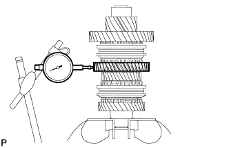
| 29. INSPECT 1ST DRIVEN GEAR RADIAL CLEARANCE |
Using a dial indicator, measure the radial clearance.
- Standard radial clearance:
- 0.015 to 0.068 mm (0.0006 to 0.0027 in.)
- Maximum radial clearance:
- 0.068 mm (0.0027 in.)
 |
| 30. INSPECT 2ND DRIVEN GEAR THRUST CLEARANCE |
Using a dial indicator, measure the thrust clearance.
- Standard thrust clearance:
- 0.11 to 0.46 mm (0.0043 to 0.0181 in.)
- Maximum thrust clearance:
- 0.46 mm (0.0181 in.)
 |
| 31. INSPECT 2ND DRIVEN GEAR RADIAL CLEARANCE |
Using a dial indicator, measure the radial clearance.
- Standard radial clearance:
- 0.015 to 0.048 mm (0.0006 to 0.0019 in.)
- Maximum radial clearance:
- 0.048 mm (0.0019 in.)
 |
| 32. INSTALL 4TH DRIVEN GEAR |
Install the output shaft spacer into the No. 1 output shaft.
 |
Coat the 4th driven gear needle roller bearing with gear oil, and install it into the No. 1 output shaft.
 |
Coat the 4th driven gear with gear oil, and install it into the No. 1 output shaft.
 |
| 33. INSTALL NO. 2 TRANSMISSION CLUTCH HUB |
Apply gear oil to the sleeve and hub.
 |
Install the clutch hub sleeve to the clutch hub.
Install the 3 shifting keys to the clutch hub.
Install the 3 shifting key springs to the clutch hub.
Place the balls in the holes of the shifting keys, and install the hub sleeve while pushing in the balls.
- NOTICE:
- Take care to prevent the balls from scattering.
Coat the 4th driven gear synchronizer ring set with gear oil.
 |
Using SST and a press, press the clutch hub into the 4th driven gear.
- SST
- 09309-14010
- NOTICE:
- After installation, make sure that the gear and synchronizer ring move smoothly.
- HINT:
- Make sure that the protruding part on the synchronizer ring is fitted into the groove of the clutch hub.
| 34. INSTALL SHAFT SNAP RING |
Using the table below, select a new snap ring that makes the thrust clearance of the No. 2 transmission clutch hub less than 0.1 mm (0.004 in.).
- Standard snap ring thickness:
Mark Thickness Mark Thickness 1 2.25 to 2.30 mm (0.0886 to 0.0906 in.) 4 2.40 to 2.45 mm (0.0945 to 0.0965 in.) 2 2.30 to 2.35 mm (0.0906 to 0.0925 in.) 5 2.45 to 2.50 mm (0.0965 to 0.0984 in.) 3 2.35 to 2.40 mm (0.0925 to 0.0945 in.) 6 2.50 to 2.55 mm (0.0984 to 0.1004 in.)
 |
Using a brass bar and hammer, tap the snap ring into the No. 1 output shaft.
 |
| 35. INSPECT 4TH DRIVEN GEAR THRUST CLEARANCE |
Using a feeler gauge, measure the thrust clearance.
- Standard thrust clearance:
- 0.10 to 0.65 mm (0.0039 to 0.0256 in.)
- Maximum thrust clearance:
- 0.65 mm (0.0256 in.)
 |
| 36. INSPECT 4TH DRIVEN GEAR RADIAL CLEARANCE |
Using a dial indicator, measure the radial clearance.
- Standard radial clearance:
- 0.015 to 0.066 mm (0.0006 to 0.0026 in.)
- Maximum radial clearance:
- 0.066 mm (0.0026 in.)
 |
| 37. INSTALL 3RD DRIVEN GEAR |
Coat the 3rd driven gear synchronizer ring set with gear oil, and install it into the No. 1 output shaft.
 |
Coat the needle roller bearing with gear oil, and install it into the No. 1 output shaft.
 |
Install the output shaft spacer into the No. 1 output shaft.
 |
Coat the 3rd driven gear with gear oil, and install it into the No. 1 output shaft.
 |
| 38. INSTALL OUTPUT SHAFT FRONT BEARING |
Using SST and a press, press the output shaft front bearing into the No. 1 output shaft.
- SST
- 09308-14010
- HINT:
- When pressing in the bearing, apply force to only the inner race. Do not apply force to the seal.
- NOTICE:
- After installation, make sure that the gear and synchronizer ring move smoothly.
 |
| 39. INSTALL OUTPUT SHAFT BEARING SHAFT SNAP RING |
Using the table below, select a new snap ring that makes the thrust clearance of the output shaft bearing less than 0.1 mm (0.004 in.).
- Standard snap ring thickness:
Mark Thickness Mark Thickness B 1.85 to 1.90 mm (0.0728 to 0.0748 in.) 0 2.05 to 2.10 mm (0.0807 to 0.0827 in.) C 1.90 to 1.95 mm (0.0748 to 0.0768 in.) 1 2.10 to 2.15 mm (0.0827 to 0.0846 in.) D 1.95 to 2.00 mm (0.0768 to 0.0787 in.) 2 2.15 to 2.20 mm (0.0846 to 0.0866 in.) E 2.00 to 2.05 mm (0.0787 to 0.0807 in.) - -
 |
Using a snap ring expander, install the snap ring onto the No. 1 output shaft.
 |
| 40. INSPECT 3RD DRIVEN GEAR THRUST CLEARANCE |
Using a feeler gauge, measure the thrust clearance.
- Standard thrust clearance:
- 0.11 to 0.54 mm (0.0043 to 0.0213 in.)
- Maximum thrust clearance:
- 0.54 mm (0.0213 in.)
 |
| 41. INSPECT 3RD DRIVEN GEAR RADIAL CLEARANCE |
Using a dial indicator, measure the radial clearance.
- Standard radial clearance:
- 0.015 to 0.066 mm (0.0006 to 0.0026 in.)
- Maximum radial clearance:
- 0.066 mm (0.0026 in.)
 |