POWER WINDOW CONTROL SYSTEM > TERMINALS OF ECU |

for Preparation Click here
| CHECK POWER WINDOW REGULATOR MOTOR ASSEMBLY (ON DRIVER DOOR) (POWER WINDOW ECU) |

Disconnect the H4*1 or G9*2 motor connector (on the driver side).
Measure the resistance and voltage of the wire harness side connector.
for LHD Symbols (Terminal No.) Wiring Color Terminal Description Condition Specified Condition GND (H4-1) - Body ground W-B - Body ground Ground Always Below 1 Ω B (H4-2) - GND (H4-1) GR - W-B Battery power supply Always 9 to 14 V UP (H4-10) - DOWN (H4-7) P - W Driver side door power window regulator motor UP DOWN Always Below 1 Ω
If the result is not as specified, there may be a malfunction on the wire harness side.for RHD Symbols (Terminal No.) Wiring Color Terminal Description Condition Specified Condition GND (G9-1) - Body ground W-B - Body ground Ground Always Below 1 Ω B (G9-2) - GND (G9-1) GR - W-B Battery power supply Always 9 to 14 V UP (G9-10) - DOWN (G9-7) W - B Driver side door power window regulator motor UP DOWN Always Below 1 Ω Reconnect the H4*1 or G9*2 motor connector (on the driver side).
Measure the voltage of the connector.
for LHD Symbols (Terminal No.) Wiring Color Terminal Description Condition Specified Condition LED (H4-5) - GND (H4-1) SB - W-B Ignition power supply Ignition switch on (IG) 9 to 14 V
If the result is not as specified, the motor may have a malfunction.for RHD Symbols (Terminal No.) Wiring Color Terminal Description Condition Specified Condition LED (G9-5) - GND (G9-1) LG - W-B Ignition power supply Ignition switch on (IG) 9 to 14 V
| CHECK POWER WINDOW REGULATOR MASTER SWITCH ASSEMBLY |
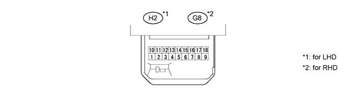
Disconnect the H2*1 or G8*2 switch connector.
Measure the resistance and voltage of the wire harness side connector.
for LHD Symbols (Terminal No.) Wiring Color Terminal Description Condition Specified Condition E (H2-1) - Body ground W-B - Body ground Ground Always Below 1 Ω B (H2-6) - Body ground L - Body ground Ignition power supply Ignition switch on (IG) 9 to 14 V B (H2-6) - Body ground L - Body ground Ignition power supply Ignition switch off Below 1 V
If the result is not as specified, there may be a malfunction on the wire harness side.for RHD Symbols (Terminal No.) Wiring Color Terminal Description Condition Specified Condition E (G8-9) - Body ground W-B - Body ground Ground Always Below 1 Ω B (G8-6) - Body ground L - Body ground Ignition power supply Ignition switch on (IG) 9 to 14 V B (G8-6) - Body ground L - Body ground Ignition power supply Ignition switch off Below 1 V Reconnect the H2*1 or G8*2 switch connector.
Reset the power window regulator motor.
Measure the voltage of the connector.
for LHD Symbols (Terminal No.) Wiring Color Terminal Description Condition Specified Condition U (H2-8) - E (H2-1) P - W-B Driver side door power window regulator motor UP output Ignition switch on (IG), driver power window regulator switch off 9 to 14 V U (H2-8) - E (H2-1) P - W-B Driver side door power window regulator motor UP output Ignition switch on (IG), driver side power window regulator switch UP (manual operation) 9 to 14 V → Below 1 V U (H2-8) - E (H2-1) P - W-B Driver side door power window regulator motor UP output Ignition switch on (IG), driver side power window fully open → driver side power window regulator switch UP (AUTO operation) → driver side power window fully closed Below 1 V → 9 to 14 V → Below 1 V D (H2-5) - E (H2-1) W - W-B Driver side door power window regulator motor DOWN output Ignition switch on (IG), driver side power window regulator switch DOWN (manual operation) Below 1 V → 9 to 14 V D (H2-5) - E (H2-1) W - W-B Driver side door power window regulator motor DOWN output Ignition switch on (IG), driver side power window fully closed → driver side power window regulator switch DOWN (AUTO operation) → driver side power window fully open Below 1 V → 9 to 14 V → Below 1 V for RHD Symbols (Terminal No.) Wiring Color Terminal Description Condition Specified Condition U (G8-1) - E (G8-9) W - W-B Driver side door power window regulator motor UP output Ignition switch on (IG), driver power window regulator switch off 9 to 14 V U (G8-1) - E (G8-9) W - W-B Driver side door power window regulator motor UP output Ignition switch on (IG), driver side power window regulator switch UP (manual operation) 9 to 14 V → Below 1 V U (G8-1) - E (G8-9) W - W-B Driver side door power window regulator motor UP output Ignition switch on (IG), driver side power window fully open → driver side power window regulator switch UP (AUTO operation) → driver side power window fully closed Below 1 V → 9 to 14 V → Below 1 V D (G8-5) - E (G8-9) B - W-B Driver side door power window regulator motor DOWN output Ignition switch on (IG), driver side power window regulator switch off → DOWN (manual operation) Below 1 V → 9 to 14 V D (G8-5) - E (G8-9) B - W-B Driver side door power window regulator motor DOWN output Ignition switch on (IG), driver side power window fully closed → driver side power window regulator switch DOWN (AUTO operation) → driver side power window fully open Below 1 V → 9 to 14 V → Below 1 V
| CHECK POWER WINDOW REGULATOR SWITCH (for Passenger Side) |

Disconnect the G3*1 or H8*2 switch connector.
Measure the voltage of the wire harness side connector.
for LHD Symbols (Terminal No.) Wiring Color Terminal Description Condition Specified Condition B (G3-3) - Body ground L - Body ground Ignition power supply Ignition switch on (IG) 9 to 14 V
If the result is not as specified, there may be a malfunction on the wire harness side.for RHD Symbols (Terminal No.) Wiring Color Terminal Description Condition Specified Condition B (H8-3) - Body ground L - Body ground Ignition power supply Ignition switch on (IG) 9 to 14 V Reconnect the G3*1 or H8*2 switch connector.
Measure the voltage of the wire harness side connector.
for LHD Symbols (Terminal No.) Wiring Color Terminal Description Condition Specified Condition B (G3-3) - D (G3-1) L - B Passenger side door power window regulator motor UP output Ignition switch on (IG), front passenger window regulator switch off Below 1 V B (G3-3) - D (G3-1) L - B Passenger side door power window regulator motor UP output Ignition switch on (IG), front passenger window regulator switch UP 9 to 14 V B (G3-3) - U (G3-4) L - Y Passenger side door power window regulator motor DOWN output Ignition switch on (IG), front passenger window regulator switch off Below 1 V B (G3-3) - U (G3-4) L - Y Passenger side door power window regulator motor DOWN output Ignition switch on (IG), front passenger window regulator switch DOWN 9 to 14 V
If the result is not as specified, there may be a malfunction.for RHD Symbols (Terminal No.) Wiring Color Terminal Description Condition Specified Condition B (H8-3) - D (H8-1) L - W Passenger side door power window regulator motor UP output Ignition switch on (IG), front passenger window regulator switch off Below 1 V B (H8-3) - D (H8-1) L - W Passenger side door power window regulator motor UP output Ignition switch on (IG), front passenger window regulator switch UP 9 to 14 V B (H8-3) - U (H8-4) L - P Passenger side door power window regulator motor DOWN output Ignition switch on (IG), front passenger window regulator switch off Below 1 V B (H8-3) - U (H8-4) L - P Passenger side door power window regulator motor DOWN output Ignition switch on (IG), front passenger window regulator switch DOWN 9 to 14 V
| CHECK POWER WINDOW REGULATOR SWITCH (for Rear Door Side) |
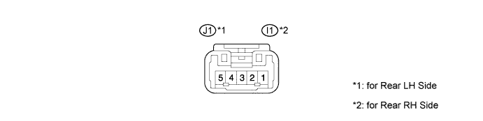
Disconnect the J1 or I1 switch connectors.
Measure the voltage of the wire harness side connector.
If the result is not as specified, there may be a malfunction on the wire harness side.Symbols (Terminal No.) Wiring Color Terminal Description Condition Specified Condition B (3) - Body ground L - Body ground Ignition power supply Ignition switch off Below 1 V B (3) - Body ground L - Body ground Ignition power supply Ignition switch on (IG) 10 to 14 V U (4) - Body ground R - Body ground Power window motor UP output Ignition switch on (IG), power window switch off → UP Below 1 V → 10 to 14 V D (1) - Body ground G - Body ground Power window motor DOWN output Ignition switch on (IG), power window switch off → DOWN Below 1 V → 10 to 14 V SU (5) - Body ground G - Body ground Power window motor UP input (Remote) Ignition switch on (IG), power window master switch off → UP (Remote) Below 1 V → 10 to 14 V SD (2) - Body ground BR - Body ground Power window motor DOWN input (Remote) Ignition switch on (IG), power window master switch off → UP (Remote) Below 1 V → 10 to 14 V
| CHECK INSTRUMENT PANEL JUNCTION BLOCK (MAIN BODY ECU) |
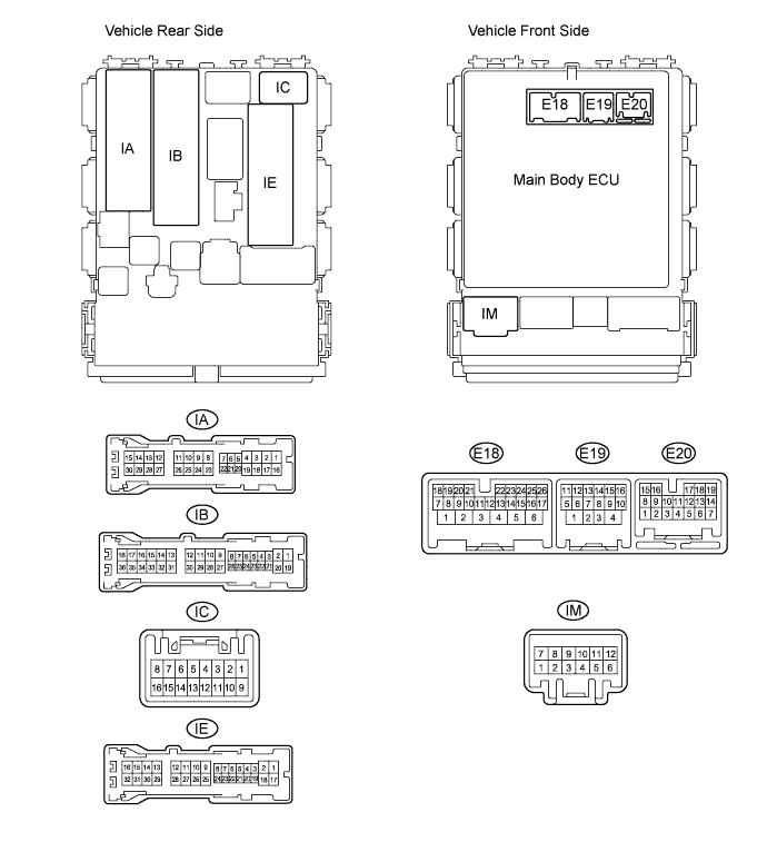
Disconnect the IA, IB and IE junction block connectors.
Disconnect the E18 ECU connector.
Measure the voltage and resistance of the wire harness side connectors.
*1: for LHDSymbols (Terminal No.) Wiring Color Terminal Description Condition Specified Condition BECU (IB-30) - GND1 (IE-17) R - W-B Battery (power supply) Always 9 to 14 V IG (IM-9) - GND1 (IE-17) W - W-B Ignition power supply Ignition switch on (IG) 9 to 14 V IG (IM-9) - GND1 (IE-17) W - W-B Ignition power supply Ignition switch off Below 1 V DCTY (IA-21) - Body ground*1 W - Body ground Driver side door courtesy light switch input Driver side door closed 10 kΩ or higher DCTY (IA-21) - Body ground*1 W - Body ground Driver side door courtesy light switch input Driver side door open Below 1 Ω PCTY (IC-14) - Body ground*1 BR - Body ground Front passenger side door courtesy light switch input Front passenger side door closed 10 kΩ or higher PCTY (IC-14) - Body ground*1 BR - Body ground Front passenger side door courtesy light switch input Front passenger side door open Below 1 Ω DCTY (IC-6) - Body ground*2 BR - Body ground Driver side door courtesy light switch input Driver side door closed 10 kΩ or higher DCTY (IC-6) - Body ground*2 BR - Body ground Driver side door courtesy light switch input Driver side door open Below 1 Ω PCTY (IA-24) - Body ground*2 W - Body ground Front passenger side door courtesy light switch input Front passenger side door closed 10 kΩ or higher PCTY (IA-24) - Body ground*2 W - Body ground Front passenger side door courtesy light switch input Front passenger side door open Below 1 Ω LIN2 (E18-23) - Body ground V - Body ground LIN communication Always 10 kΩ or higher GND1 (IE-17) - Body ground W-B - Body ground Ground Always Below 1 Ω
*2: for RHD
If the result is not as specified, there may be a malfunction on the wire harness side.