AIRBAG SYSTEM > Trouble in Passenger Airbag ON/OFF Indicator |

for Preparation Click here
DESCRIPTION
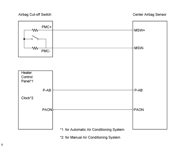
When the airbag cut-off switch is turned off, the passenger airbag OFF indicator illuminates. When the passenger airbag OFF indicator illuminates, both the front passenger airbag and the front passenger side front seat side airbag stop functioning.WIRING DIAGRAM
INSPECTION PROCEDURE
| 1.CHECK SRS WARNING LIGHT |
Turn the ignition switch on (IG), and check the SRS warning light condition.
- OK:
- The SRS warning light does not come on.
|
| ||||
| OK | |
| 2.CHECK CONNECTOR |
Turn the ignition switch off.
Disconnect the cable from the negative (-) battery terminal, and wait for at least 90 seconds.
Check that the connectors are properly connected to the center airbag sensor and the airbag cut-off switch.
- OK:
- The connectors are properly connected.
|
| ||||
| OK | |
| 3.INSPECT AIRBAG CUT-OFF SWITCH |
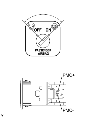 |
Disconnect the E68 passenger airbag manual cut-off switch connector.
Measure the resistance of the wire harness side connector.
- Standard resistance:
Tester Connection Switch Condition Specified Condition 1 (PMC-) - 2 (PMC+) OFF 80 to 120 Ω 1 (PMC-) - 2 (PMC+) ON 320 to 480 Ω
|
| ||||
| OK | |
| 4.CHECK INSTRUMENT PANEL WIRE (FOR OPEN) |
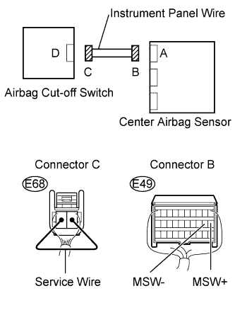 |
Disconnect the instrument panel wire connector from the airbag cut-off switch.
Using a service wire, connect E68-1 (PMC-) and E68-2 (PMC+) of connector C.
- NOTICE:
- Do not forcibly insert the service wire into the terminals of the connector when connecting.
Measure the resistance of the wire harness side connector.
- Standard resistance:
Tester Connection Specified Condition E49-11 (MSW+) - E49-12 (MSW-) Below 1 Ω
|
| ||||
| OK | |
| 5.CHECK INSTRUMENT PANEL WIRE (FOR SHORT) |
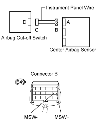 |
Disconnect the service wire from connector C.
Measure the resistance of the wire harness side connector.
- Standard resistance:
Tester Connection Specified Condition E49-11 (MSW+) - E49-12 (MSW-) 1 MΩ or higher
|
| ||||
| OK | |
| 6.CHECK INSTRUMENT PANEL WIRE (TO B+) |
|
Connect the cable to the negative (-) battery terminal, and wait for at least 2 seconds.
Turn the ignition switch on (IG).
Measure the voltage of the wire harness side connector.
- Standard voltage:
Tester Connection Specified Condition E49-11 (MSW+)- Body ground Below 1 V E49-12 (MSW-) - Body ground Below 1 V
|
| ||||
| OK | |
| 7.CHECK INSTRUMENT PANEL WIRE (TO GROUND) |
|
Turn the ignition switch off.
Disconnect the cable from the negative (-) battery terminal, and wait for at least 90 seconds.
Measure the resistance of the wire harness side connector.
- Standard resistance:
Tester Connection Specified Condition E49-11 (MSW+) - Body ground 1 MΩ or higher E49-12 (MSW-) - Body ground 1 MΩ or higher
|
| ||||
| OK | ||
| ||