EXHAUST HEAT RECIRCULATION SYSTEM > Exhaust Heat Recirculation System Circuit |

for Preparation Click here
DESCRIPTION
In the exhaust heat recirculation system, coolant is warmed up using exhaust gas heat to accelerate engine warm-up time, enhancing fuel efficiency and heater performance.The heat recirculator is positioned in the front exhaust pipe assembly after the catalyst. Coolant from the engine flows around the heat recirculator and then returns to the engine. If the engine is started while the engine is cold, the exhaust pipe gas control actuator sub-assembly rod is contracted and the exhaust flow control valve is closed, routing the exhaust gas around the heat recirculator to warm up the coolant.
After the engine coolant temperature rises and the engine has warmed up, the heat of the coolant expands the thermostat and the exhaust pipe gas control actuator sub-assembly rod extends. This opens the exhaust flow control valve to switch to the normal exhaust gas path.
The exhaust flow control valve can also be opened by exhaust gas pressure to prevent insufficient acceleration performance when the engine is cold. In addition, to monitor the engine coolant temperature, an engine coolant temperature sensor (for exhaust heat recirculation system) is provided between the engine and the heat recirculator. The engine coolant temperature sensor (for exhaust heat recirculation system) has a built-in thermistor with a resistance that varies according to the temperature of the engine coolant. When the engine coolant temperature becomes low, the resistance of the thermistor increases. When the temperature becomes high, the resistance drops. These variations in resistance are transmitted to the combination meter assembly as voltage changes. When the temperature becomes high (overheating), the engine coolant temperature sensor sends a signal to the combination meter assembly and illuminates or blinks the water temperature indicator light in the combination meter assembly.
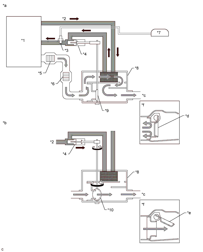
| *1 | Engine Assembly | *2 | Engine Coolant |
| *3 | Engine Coolant Temperature Sensor (for Exhaust Heat Recirculation System) | *4 | Exhaust Pipe Gas Control Actuator Sub-assembly |
| *5 | Front Catalyst | *6 | Rear Catalyst |
| *7 | Combination Meter Assembly | *8 | Front Exhaust Pipe Assembly |
| *9 | Exhaust Flow Control Valve (Valve Closed) | *10 | Exhaust Flow Control Valve (Valve Open) |
| *a | Exhaust Flow Control Valve (Valve Closed) | *b | Exhaust Flow Control Valve (Valve Open) |
| *c | Exhaust Gas | *d | Valve Closed |
| *e | Valve Open | *f | Side View |
WIRING DIAGRAM
Refer to System Diagram (Click here).INSPECTION PROCEDURE
| 1.CHECK HARNESS AND CONNECTOR (ENGINE COOLANT TEMPERATURE SENSOR - COMBINATION METER ASSEMBLY) |
Disconnect the engine coolant temperature sensor (for exhaust heat recirculation system) connector.
Disconnect the combination meter assembly connector.
Measure the resistance according to the value(s) in the table below.
- Standard Resistance:
Tester Connection Condition Specified Condition A30-2 (TWS3) - G1-15 (TWS3) Always Below 1 Ω A30-1 (E2) - G1-36 (E2) Always Below 1 Ω A30-2 (TWS3) or G1-15 (TWS3) - Body ground Always 10 kΩ or higher
|
| ||||
| OK | |
| 2.INSPECT ENGINE COOLANT TEMPERATURE SENSOR (FOR EXHAUST HEAT RECIRCULATION SYSTEM) |
Inspect the engine coolant temperature sensor (for exhaust heat recirculation system) (Click here).
|
| ||||
| OK | ||
| ||