POWER STEERING SYSTEM > TS and CG Terminal Circuit |

for Preparation Click here
DESCRIPTION
In Test Mode (signal check), a malfunction in a speed sensor that cannot be detected when the vehicle is stopped can be detected while driving.Sensor check mode can be entered by connecting terminals TS and CG of the DLC3 and turning the ignition switch from off to ON (IG).
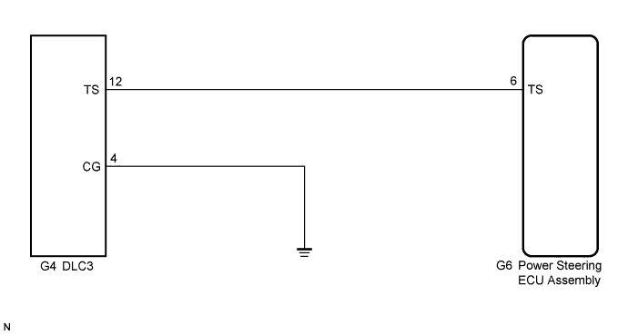
WIRING DIAGRAM
INSPECTION PROCEDURE
- NOTICE:
- If the power steering ECU assembly has been replaced with a new one, perform assist map writing and torque sensor zero point calibration (Click here).
| 1.CHECK HARNESS AND CONNECTOR (POWER STEERING ECU ASSEMBLY - TS of DLC3) |
Disconnect the power steering ECU assembly connector.
Measure the resistance according to the value(s) in the table below.
- Standard Resistance:
Tester Connection Condition Specified Condition G6-6 (TS) - G4-12 (TS) Always Below 1 Ω G6-6 (TS) - Body ground Always 10 kΩ or higher
|
| ||||
| OK | |
| 2.CHECK HARNESS AND CONNECTOR (CG of DLC3 - BODY GROUND) |
Measure the resistance according to the value(s) in the table below.
- Standard Resistance:
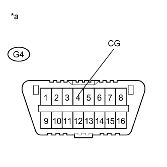
Tester Connection Condition Specified Condition G4-4 (CG) - Body ground Always Below 1 Ω
Text in Illustration *a Front view of DLC3
 |
|
| ||||
| OK | ||
| ||