STEERING PAD SWITCH > INSPECTION |

for Preparation Click here
| 1. INSPECT STEERING PAD SWITCH LH (w/o Multi-information Display) |
Measure the resistance according to the value(s) in the table below.
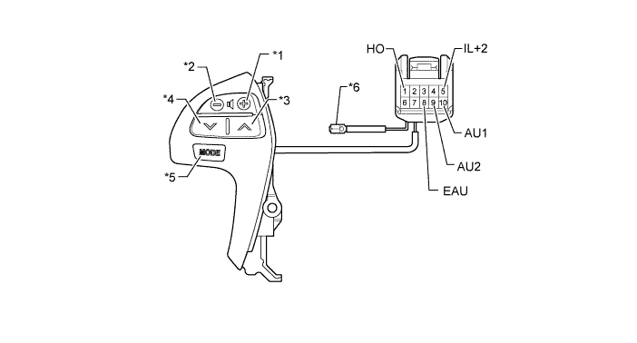
Text in Illustration *1 Volume+ Switch *2 Volume- Switch *3 Seek+ Switch *4 Seek- Switch *5 MODE Switch *6 Horn Wire - Standard Resistance:
Tester Connection Switch Condition Specified Condition 9 (AU2) - 8 (EAU) No switch pushed 95 to 105 kΩ 9 (AU2) - 8 (EAU) MODE switch pushed Below 2.5 Ω 10 (AU1) - 8 (EAU) No switch pushed 95 to 105 kΩ 10 (AU1) - 8 (EAU) Seek+ switch pushed Below 2.5 Ω 10 (AU1) - 8 (EAU) Seek- switch pushed 312.6 to 345.5 Ω 10 (AU1) - 8 (EAU) Volume+ switch pushed 950 to 1050 Ω 10 (AU1) - 8 (EAU) Volume- switch pushed 2954.5 to 3265.5 Ω 1 (HO) - Horn wire Always Below 2.5 Ω
Check the illumination.
Connect the battery positive (+) lead to terminal IL+2 and the negative (-) lead to terminal EAU of the steering pad switch assembly connector.
Check that the switch illumination comes on.
- OK:
- Steering pad switch illumination comes on.
| 2. INSPECT STEERING PAD SWITCH ASSEMBLY (w/ Multi-information Display) |
Measure the resistance according to the value(s) in the table below.
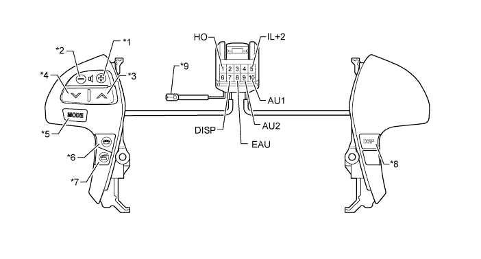
Text in Illustration *1 Volume+ Switch *2 Volume- Switch *3 Seek+ Switch *4 Seek- Switch *5 MODE Switch *6 On Hook Switch *7 Off Hook Switch *8 DISP Switch *9 Horn Wire - - - Standard Resistance:
Tester Connection Switch Condition Specified Condition 9 (AU2) - 8 (EAU) No switch pushed 95 to 105 kΩ 9 (AU2) - 8 (EAU) MODE switch pushed Below 2.5 Ω 9 (AU2) - 8 (EAU) On hook switch pushed 312.6 to 345.5 Ω 9 (AU2) - 8 (EAU) Off hook switch pushed 950 to 1050 Ω 10 (AU1) - 8 (EAU) No switch pushed 95 to 105 kΩ 10 (AU1) - 8 (EAU) Seek+ switch pushed Below 2.5 Ω 10 (AU1) - 8 (EAU) Seek- switch pushed 312.6 to 345.5 Ω 10 (AU1) - 8 (EAU) Volume+ switch pushed 950 to 1050 Ω 10 (AU1) - 8 (EAU) Volume- switch pushed 2954.5 to 3265.5 Ω 7 (DISP) - 8 (EAU) DISP switch pushed Below 2.5 Ω 1 (HO) - Horn wire Always Below 2.5 Ω
Connect the battery positive (+) lead to terminal IL+2 and the negative (-) lead to terminal EAU of the steering pad switch assembly connector.
Check that the switch illumination comes on.
- OK:
- Steering pad switch illumination comes on.