AUTOMATIC TRANSMISSION SYSTEM > L4 Position Switch Circuit |

for Preparation Click here
DESCRIPTION
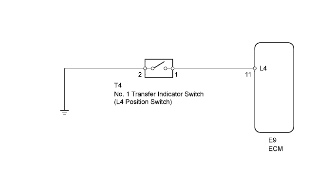
The No. 1 transfer indicator switch (L4 position switch) detects the gear position of the transfer shift lever.Moving the transfer shift lever to L4 turns the L4 position switch ON. Then the ECM cancels operation of the lock-up clutch.
WIRING DIAGRAM
INSPECTION PROCEDURE
| 1.CHECK WIRE HARNESS (NO. 1 TRANSFER INDICATOR SWITCH - BODY GROUND) |
Disconnect the T4 switch connector.
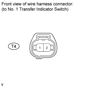 |
Measure the resistance of the wire harness side connector.
- Standard resistance:
Tester Connection Condition Specified Condition T4-2 - Body ground Always Below 1 Ω
|
| ||||
| OK | |
| 2.INSPECT NO. 1 TRANSFER INDICATOR SWITCH (L4 POSITION SWITCH) |
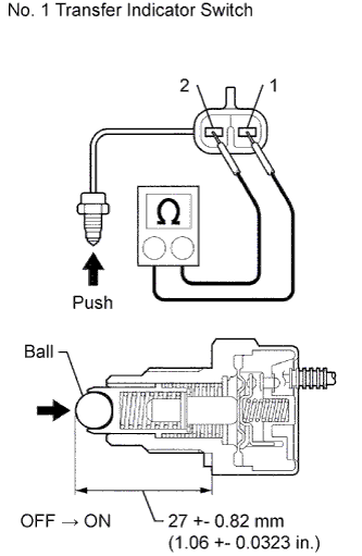 |
Remove the transfer indicator switch.
Measure the resistance of the switch when pushing the ball at the tip of the switch.
- Standard resistance:
Tester Connection Switch Condition Specified Condition 1 - 2 Not pushed 10 kΩ or higher 1 - 2 Pushed Below 1 Ω
|
| ||||
| OK | |
| 3.CHECK WIRE HARNESS (NO. 1 TRANSFER INDICATOR SWITCH - ECM) |
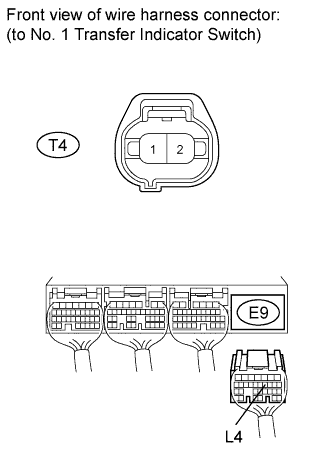 |
Disconnect the T4 switch connector.
Disconnect the E9 ECM connector.
Measure the resistance of the wire harness side connectors.
- Standard resistance:
Tester Connection Condition Specified Condition E9-11 (L4) - T4-1 Always Below 1 Ω E9-11 (L4) or T4-1 - Body ground Always 10 kΩ or higher
|
| ||||
| OK | ||
| ||