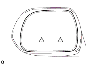
OUTER REAR VIEW MIRROR > INSTALLATION |

for Preparation Click here
- HINT:
- Use the same procedure for RHD and LHD vehicles.
- The procedure listed below is for LHD vehicles.
- Use the same procedure for the RH and LH sides.
- The procedure listed below is for the LH side.
- A bolt without a torque specification is shown in the standard bolt chart (Click here).
| 1. INSTALL OUTER MIRROR COVER LH (w/o Side Turn Signal Light) |
Attach the 3 claws as shown in the illustration.
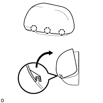 |
Attach the 6 claws to install the mirror cover LH.
After installing the outer mirror cover, check that there is no gap between the cover and mirror body.
- HINT:
- If there is a gap between the cover and body, noise will occur during driving.
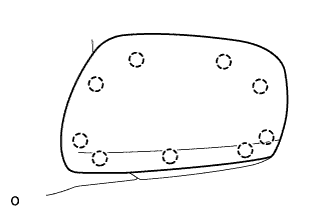 |
| 2. INSTALL OUTER MIRROR COVER LH (w/ Side Turn Signal Light) |
Attach the 2 claws as shown in the illustration.
Attach the 6 claws to install the outer mirror cover LH.
After installing the outer mirror cover, check that there is no gap between the cover and mirror body.
If there is a gap between the cover and body, noise will occur during driving.
 |
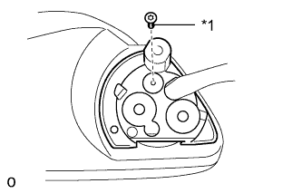
Using a T25 "TORX" socket wrench, install the screw.
- HINT:
- Clean the threads of the screw with non-residue solvent.
- Apply adhesive to the threads of the screw.
- Adhesive:
- Toyota Genuine Adhesive 1324, Three Bond 1324 or equivalent
Text in Illustration *1 Adhesive
 |
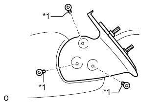
Using a T25 "TORX" socket wrench, install the screws.
- HINT:
- Clean the threads of the screws with non-residue solvent.
- Apply adhesive to the threads of the screws.
- Adhesive:
- Toyota Genuine Adhesive 1324, Three Bond 1324 or equivalent
Text in Illustration *1 Adhesive
 |
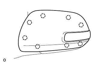
Attach the 5 claws.
Install the rubber base with the screw.
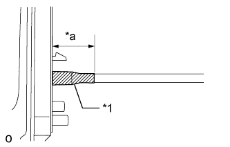
Apply new tape as shown in the illustration.
Text in Illustration *1 Tape *a 40 mm (1.58 in.)
 |
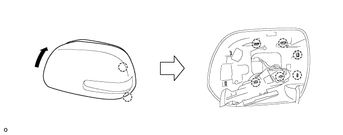
| 3. INSTALL OUTER MIRROR LH |
Attach the 2 claws as shown in the illustration.
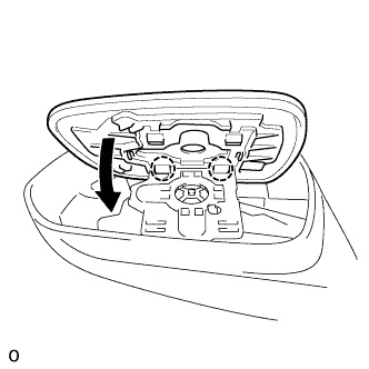 |
Attach the 2 clips to install the outer mirror LH.
- NOTICE:
- Do not push in the glass with excessive force. Doing so may break the mirror surface.
 |
| 4. INSTALL OUTER REAR VIEW MIRROR ASSEMBLY LH |
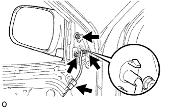 |
Install the outer rear view mirror assembly LH with the 3 nuts.
- Torque:
- 8.0 N*m{ 82 kgf*cm , 71 ft.*lbf }
w/ Power Mirror Control System:
Connect the connector.
| 5. INSTALL FRONT DOOR TRIM BOARD SUB-ASSEMBLY LH |
for Double Cab:
Attach the 8 clips to install the front door trim board.
Install the screw and clip.
for Single Cab, for Extra Cab:
Attach the 9 clips to install the front door trim board.
Install the screw and clip.
| 6. INSTALL DOOR PULL HANDLE |
Install the door pull handle with the screw.
| 7. INSTALL FRONT DOOR LOWER FRAME BRACKET GARNISH LH |
Attach the 2 clips to install the front door lower frame bracket garnish.
| 8. INSTALL POWER WINDOW REGULATOR SWITCH ASSEMBLY WITH FRONT DOOR ARMREST BASE PANEL RH (w/ Power Window) |
Connect the connector.
Attach the 4 claws and 2 clips to install the power window regulator master switch assembly with front door armrest base panel.
| 9. INSTALL POWER WINDOW REGULATOR MASTER SWITCH ASSEMBLY WITH FRONT DOOR ARMREST BASE PANEL LH (w/ Power Window) |
Connect the connector.
Attach the 4 claws and 2 clips to install the power window regulator switch assembly with front door armrest base panel.
| 10. INSTALL FRONT DOOR WINDOW REGULATOR HANDLE ASSEMBLY (w/o Power Window) |
Temporarily install the front door window regulator handle, fully close the window, and then remove the front door window regulator handle.
Install the plate and snap ring to the front door window regulator handle.
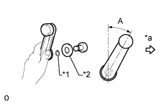 |
Install the front door window regulator handle to the front door window regulator as shown in the illustration.
Text in Illustration *1 Snap Ring *2 Plate *a Front Side - Standard:
Area Specified Condition A 18 to 42°