BACK WINDOW GLASS > INSTALLATION |

for Preparation Click here
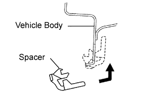
| 1. INSTALL NO. 1 BACK WINDOW GLASS STOPPER |
Install 2 new spacers to the vehicle body as shown in the illustration.
 |
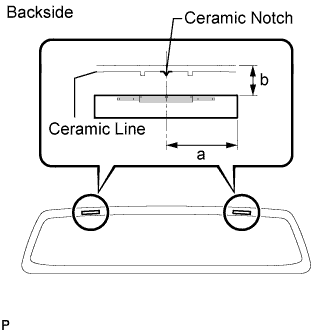
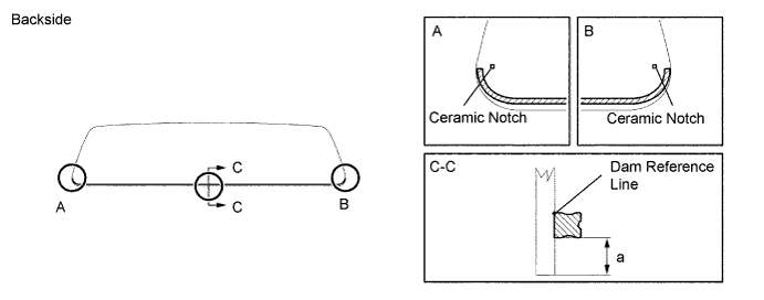
| 2. INSTALL NO. 2 BACK WINDOW GLASS STOPPER |
 |
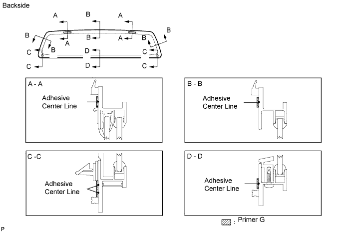
Apply Primer G to the back window glass where the stoppers will be installed.
- NOTICE:
- Allow the primer to dry for 3 minutes or more.
- Throw away any leftover primer.
- Do not apply too much primer.
- HINT:
- If the primer is applied to an area that is not specified, apply non-residue solvent to a clean cloth and wipe off the excess primer.
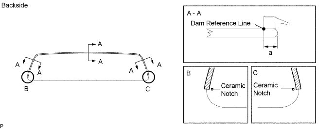
Install 2 new stoppers to the glass as shown in the illustration.
- Standard:
Area Specified Condition a 40.0 mm (1.575 in.) b 16.3 mm (0.642 in.)
| 3. INSTALL BACK WINDOW GLASS SPACER |
Apply Primer G to the back window glass where the spacers will be installed.
- NOTICE:
- Allow the primer to dry for 3 minutes or more.
- Throw away any leftover primer.
- Do not apply too much primer.
- HINT:
- If the primer is applied to an area that is not specified, apply non-residue solvent to a clean cloth and wipe off the excess primer.
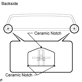 |
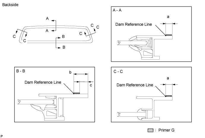
Install 2 new spacers to the back window glass as shown in the illustration.
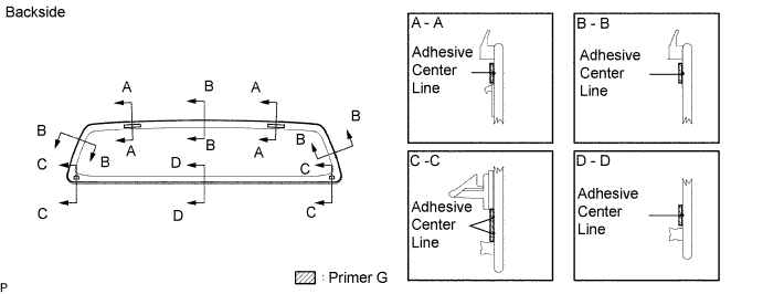
| 4. INSTALL NO. 1 BACK WINDOW MOULDING (for Fixed Type) |
Apply Primer G to the glass where the moulding and dam will be installed.
- HINT:
- If the primer is applied to an area that is not specified, apply non-residue solvent to a clean cloth and wipe off the excess primer.
- NOTICE:
- Allow the primer to dry for 3 minutes or more.
- Throw away any leftover primer.
- Do not apply too much primer.
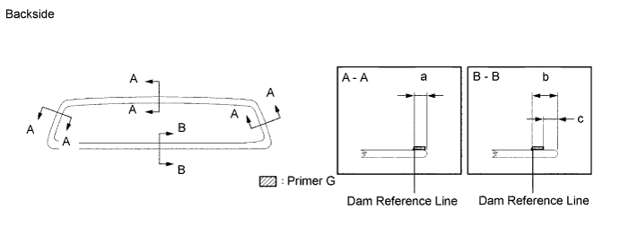
- Standard:
Area Specified Condition a 6.4 mm (0.252 in.) b 12.7 mm (0.450 in.) c 7.5 mm (0.295 in.)
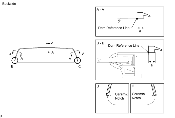
Remove the peeling paper from the adhesive part of the moulding. Install a new moulding (adhesive side) to the glass (Primer G area) as shown in the illustration.
- Standard:
Area Specified Condition a 6.4 mm (0.252 in.)
| 5. INSTALL NO. 1 BACK WINDOW MOULDING (for Slide Type) |
Apply Primer G to the glass where the moulding and dam will be installed.
- HINT:
- If the primer is applied to an area that is not specified, apply non-residue solvent to a clean cloth and wipe off the excess primer.
- NOTICE:
- Allow the primer to dry for 3 minutes or more.
- Throw away any leftover primer.
- Do not apply too much primer.
- Standard:
Area Specified Condition a 6.4 mm (0.252 in.) b 12.7 mm (0.450 in.) c 7.5 mm (0.295 in.)
Remove the peeling paper from the adhesive part of the moulding. Install a new moulding (adhesive side) to the glass (Primer G area) as shown in the illustration.
- Standard:
Area Specified Condition a 6.4 mm (0.252 in.)
| 6. INSTALL BACK WINDOW GLASS ADHESIVE DAM (for Fixed Type) |
Remove the peeling paper from the adhesive part of the dam. Install the dam (adhesive side) to the glass (Primer G area) as shown in the illustration.
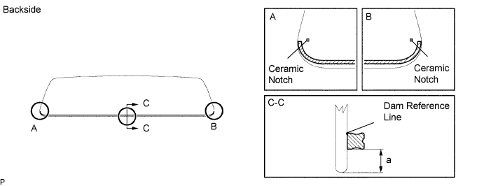
- Standard:
Area Specified Condition a 7.5 mm (0.295 in.)
| 7. INSTALL BACK WINDOW GLASS ADHESIVE DAM (for Slide Type) |
Remove the peeling paper from the adhesive part of the dam. Install the dam (adhesive side) to the glass (Primer G area) as shown in the illustration.
- Standard:
Area Specified Condition a 7.5 mm (0.295 in.)
| 8. INSTALL BACK WINDOW GLASS (for Fixed Type) |
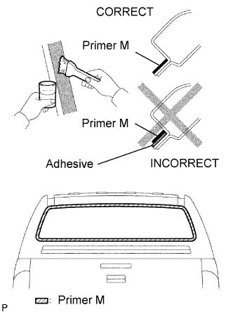 |
Using a brush, apply Primer M to the exposed part of the vehicle body.
- NOTICE:
- Allow the primer to dry for 3 minutes or more.
- Do not apply primer m to the adhesive.
- Throw away any leftover primer.
- Do not apply too much primer.
Using a brush or sponge, apply Primer G to the contact surface of the glass.
- HINT:
- If the primer is applied to an area that is not specified, apply non-residue solvent to a clean cloth and wipe off the excess primer.
- NOTICE:
- Allow the primer to dry for 3 minutes or more.
- Throw away any leftover primer.
- Do not apply too much primer.
Apply adhesive to the glass.
- Adhesive:
- Toyota Genuine Windshield Glass Adhesive or equivalent
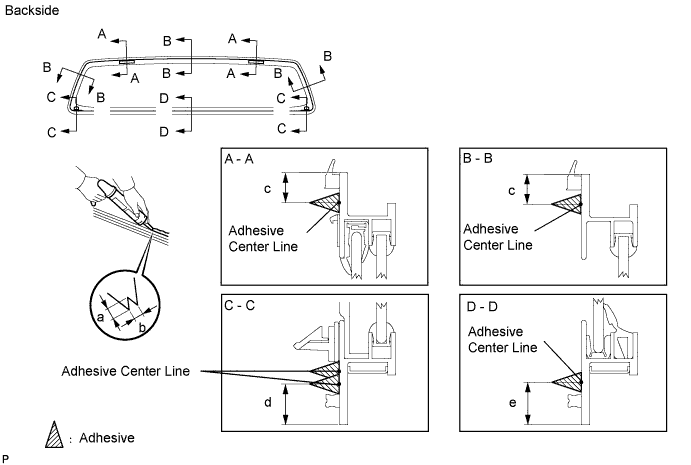
Cut off the tip of the cartridge nozzle as shown in the illustration.
- HINT:
- After cutting off the tip, use all adhesive within the time written in the table below.
- Usage Time Frame:
Temperature Usage Time Frame 35°C (95°F) 15 minutes 20°C (68°F) 1 hour 40 minutes 5°C (41°F) 8 hours
Load the sealer gun with the cartridge.
Apply adhesive to the glass as shown in the illustration.
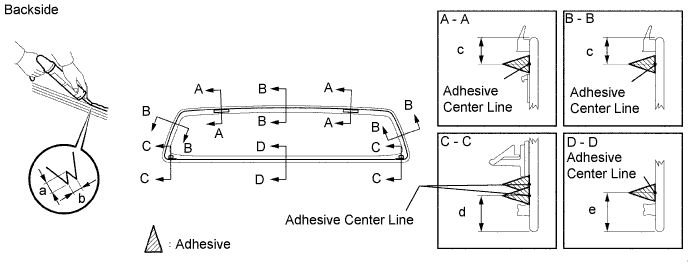
- Standard:
Area Specified Condition a 12.0 mm (0.472 in.) b 8.0 mm (0.315 in.) c 12.0 mm (0.472 in.) d 16.6 mm (0.654 in.) e 17.7 mm (0.697 in.)
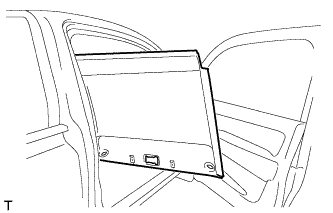
Install the glass to the vehicle body.
Lightly press the front surface of the glass to ensure that it is securely fit to the vehicle body.
- NOTICE:
- Check that the spacers are attached to the vehicle body correctly.
- Check that the vehicle body and glass have a small gap between them.
Hold the glass in place securely with protective tape or equivalent until the adhesive hardens.
- NOTICE:
- Do not drive the vehicle for the amount of time written in the table below.
- Minimum Time:
Temperature Minimum Time Prior to Driving Vehicle 35°C (95°F) 1 hour 30 minutes 20°C (68°F) 5 hours 5°C (41°F) 24 hours
| 9. INSTALL BACK WINDOW GLASS (for Slide Type) |
|
Using a brush, apply Primer M to the exposed part of the vehicle body.
- NOTICE:
- Allow the primer to dry for 3 minutes or more.
- Do not apply primer m to the adhesive.
- Throw away any leftover primer.
- Do not apply too much primer.
Using a brush or sponge, apply Primer G to the contact surface of the glass.
- HINT:
- If the primer is applied to an area that is not specified, apply non-residue solvent to a clean cloth and wipe off the excess primer.
- NOTICE:
- Allow the primer to dry for 3 minutes or more.
- Throw away any leftover primer.
- Do not apply too much primer.
Apply adhesive to the glass.
- Adhesive:
- Toyota Genuine Windshield Glass Adhesive or equivalent
Cut off the tip of the cartridge nozzle as shown in the illustration.
- HINT:
- After cutting off the tip, use all adhesive within the time written in the table below.
- Usage Time Frame:
Temperature Usage Time Frame 35°C (95°F) 15 minutes 20°C (68°F) 1 hour 40 minutes 5°C (41°F) 8 hours
Load the sealer gun with the cartridge.
Apply adhesive to the glass as shown in the illustration.
- Standard:
Area Specified Condition a 12.0 mm (0.472 in.) b 8.0 mm (0.315 in.) c 12.0 mm (0.472 in.) d 16.6 mm (0.654 in.) e 17.7 mm (0.697 in.)
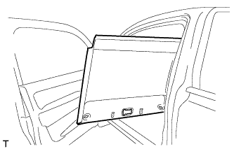
Install the glass to the vehicle body.
Lightly press the front surface of the glass to ensure that it is securely fit to the vehicle body.
- NOTICE:
- Check that the spacers are attached to the vehicle body correctly.
- Check that the vehicle body and glass have a small gap between them.
Hold the glass in place securely with protective tape or equivalent until the adhesive hardens.
- NOTICE:
- Do not drive the vehicle for the amount of time written in the table below.
- Minimum Time:
Temperature Minimum Time Prior to Driving Vehicle 35°C (95°F) 1 hour 30 minutes 20°C (68°F) 5 hours 5°C (41°F) 24 hours
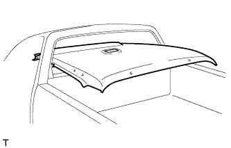
| 10. INSTALL ROOF HEADLINING ASSEMBLY (for Single Cab) |
for LHD:
Place the roof headlining into the vehicle as shown in the illustration.
- NOTICE:
- Be careful not to damage the roof headlining when placing it.
Install the roof headlining with the 5 clips.
Connect the connectors and attach the 4 clamps.
for RHD:
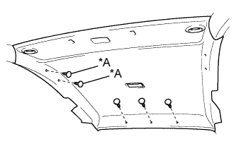
Place the roof headlining into the vehicle as shown in the illustration.
- NOTICE:
- Be careful not to damage the roof headlining when placing it.
Install the roof headlining with the clips.
Text in Illustration *A w/o Assist Grip Connect the connectors and attach the 5 clamps.
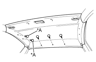
Attach the 4 clamps to the front pillar.
| 11. INSTALL NO. 1 ROOM LIGHT ASSEMBLY (for Single Cab) |
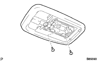 |
Connect the light connector.
Install the room light with the 2 screws.
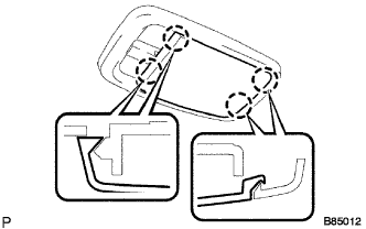
Attach the lens with the 4 claws.
 |
| 12. INSTALL ASSIST GRIP (for Single Cab) |
Install the assist grip with the 2 screws.
Attach the 4 claws to close the 2 covers.
| 13. INSTALL QUARTER INSIDE TRIM BOARD LH (for Single Cab) |
Attach the 3 clips to install the quarter inside trim board.
Connect the front seat belt shoulder anchor with the bolt.
- Torque:
- 42 N*m{ 428 kgf*cm , 31 ft.*lbf }
Attach the 2 claws to close the front seat belt shoulder anchor cover.
| 14. INSTALL QUARTER INSIDE TRIM BOARD RH (for Single Cab) |
- HINT:
- Use the same procedure described for the LH side.
| 15. INSTALL LOWER QUARTER TRIM PANEL LH (for Single Cab) |
Attach the 3 clips, claw and 2 guides to install the lower quarter trim panel.
Connect the front seat outer belt floor anchor with the bolt.
- Torque:
- 42 N*m{ 428 kgf*cm , 31 ft.*lbf }
| 16. INSTALL LOWER QUARTER TRIM PANEL RH (for Single Cab) |
- HINT:
- Use the same procedure described for the LH side.
| 17. INSTALL FRONT SEAT OUTER BELT ASSEMBLY LH (for Single Cab) |
 |
- NOTICE:
- Do not disassemble the retractor.
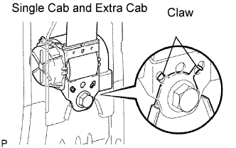
w/o Pretensioner single cab and extra cab:
Align the claws with the seat belt positioning holes and install the ELR of the seat belt with the bolt as shown in the illustration.- Torque:
- 42 N*m{ 428 kgf*cm , 31 ft.*lbf }
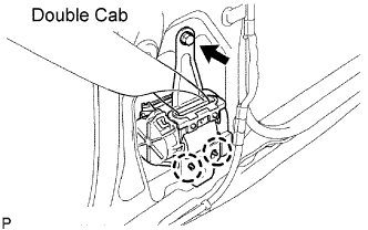
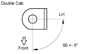
w/o Pretensioner Double cab:
Align the claws with the seat belt positioning holes and install the ELR of the seat belt with the bolt as shown in the illustration.- Torque:
- 4.8 N*m{ 49 kgf*cm , 42 in.*lbf }
 |
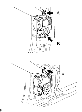
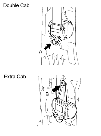
w/ Pretensioner:
Install the bolt and seat belt.- Torque:
- 4.8 N*m{ 49 kgf*cm , 42 in.*lbf } for bolt A
- Torque:
- 42 N*m{ 428 kgf*cm , 31 ft.*lbf } for bolt B
 |
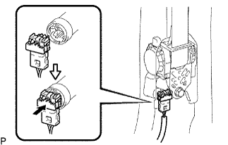
w/ Pretensioner:
Connect the pretensioner connector as shown in the illustration.
 |
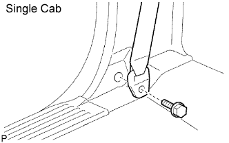
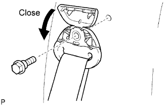
Single cab:
Install the anchor with the bolt.- Torque:
- 42 N*m{ 428 kgf*cm , 31 ft.*lbf }
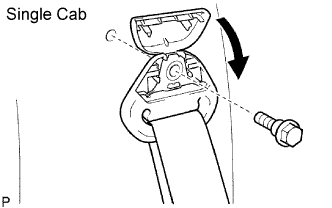 |
Close the cover.
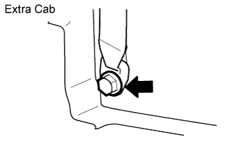
Extra cab and double cab:
Install the anchor with the bolt.- Torque:
- 42 N*m{ 428 kgf*cm , 31 ft.*lbf }
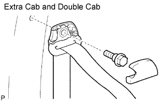 |
Install the cap.
Single cab:
Install the quarter trim panel lower. Then install the seat belt floor anchor with the bolt.- Torque:
- 42 N*m{ 428 kgf*cm , 31 ft.*lbf }
 |
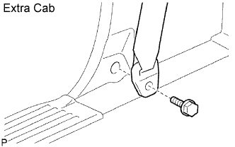
Extra cab:
Install the quarter inside trim board. Then install the seat belt floor anchor with the bolt.- Torque:
- 42 N*m{ 428 kgf*cm , 31 ft.*lbf }
 |
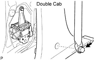
Double cab:
Install the anchor of the seat belt with the built-in bolt after installing the center pillar garnish lower.- Torque:
- 42 N*m{ 428 kgf*cm , 31 ft.*lbf }
 |
| 18. INSTALL FRONT SEAT OUTER BELT ASSEMBLY RH (for Single Cab) |
|
- NOTICE:
- Do not disassemble the retractor.
w/o Pretensioner single cab and extra cab:
Align the claws with the seat belt positioning holes and install the ELR of the seat belt with the bolt as shown in the illustration.- Torque:
- 42 N*m{ 428 kgf*cm , 31 ft.*lbf }
w/o Pretensioner Double cab:
Align the claws with the seat belt positioning holes and install the ELR of the seat belt with the bolt as shown in the illustration.- Torque:
- 4.8 N*m{ 49 kgf*cm , 42 in.*lbf }
|
w/ Pretensioner:
Install the bolt and seat belt.- Torque:
- 4.8 N*m{ 49 kgf*cm , 42 in.*lbf } for bolt A
- Torque:
- 42 N*m{ 428 kgf*cm , 31 ft.*lbf } for bolt B
|
w/ Pretensioner:
Connect the pretensioner connector as shown in the illustration.
|
Single cab:
Install the anchor with the bolt.- Torque:
- 42 N*m{ 428 kgf*cm , 31 ft.*lbf }
|
Close the cover.
Extra cab and double cab:
Install the anchor with the bolt.- Torque:
- 42 N*m{ 428 kgf*cm , 31 ft.*lbf }
|
Install the cap.
Single cab:
Install the quarter trim panel lower. Then install the seat belt floor anchor with the bolt.- Torque:
- 42 N*m{ 428 kgf*cm , 31 ft.*lbf }
|
Extra cab:
Install the quarter inside trim board. Then install the seat belt floor anchor with the bolt.- Torque:
- 42 N*m{ 428 kgf*cm , 31 ft.*lbf }
|
Double cab:
Install the anchor of the seat belt with the built-in bolt after installing the center pillar garnish lower.- Torque:
- 42 N*m{ 428 kgf*cm , 31 ft.*lbf }
|
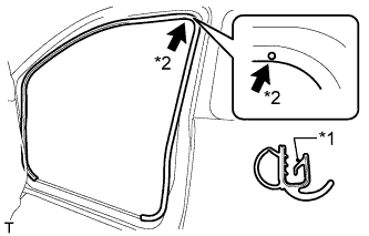
| 19. INSTALL FRONT DOOR OPENING TRIM LH (for Single Cab) |
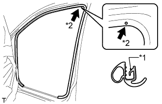 |
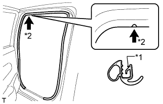
Align the paint mark on the front door opening trim with the mark position on the vehicle and install the front door opening trim as shown in the illustration.
Text in Illustration *1 Paint Mark *2 Mark Position
| 20. INSTALL FRONT DOOR OPENING TRIM RH (for Single Cab) |
- HINT:
- Use the same procedure described for the LH side.
| 21. INSTALL FRONT DOOR SCUFF PLATE LH (for Single Cab) |
Attach the 4 clips and 8 claws to install the front door scuff plate.
| 22. INSTALL FRONT DOOR SCUFF PLATE RH (for Single Cab) |
- HINT:
- Use the same procedure described for the LH side.
| 23. INSTALL UPPER BACK PANEL GARNISH (for Single Cab) |
Attach the 5 clips, 4 guides and 4 claws to install the upper back panel garnish.
| 24. INSTALL FRONT SEAT ASSEMBLY (for Single cab separate seat type) |
Install the front seat assembly (Click here).
| 25. INSTALL FRONT SEAT ASSEMBLY (for Single cab bench seat type) |
Install the front seat assembly (Click here).
| 26. INSTALL VISOR HOLDER LH (for Single Cab) |
Attach the 2 claws to install the visor holder.
Install the screw.
| 27. INSTALL VISOR HOLDER RH (for Single Cab) |
- HINT:
- Use the same procedure described for the LH side.
| 28. INSTALL VISOR ASSEMBLY LH (for Single Cab) |
Install the visor with the 2 screws.
Attach the guide.
| 29. INSTALL VISOR ASSEMBLY RH (for Single Cab) |
- HINT:
- Use the same procedure described for the LH side.
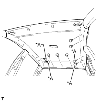
| 30. INSTALL ROOF HEADLINING ASSEMBLY (for Extra Cab) |
for LHD:
Place the roof headlining into the vehicle as shown in the illustration.
- NOTICE:
- Be careful not to damage the roof headlining when placing it.
Install the roof headlining with the 5 clips.
Connect the connectors and attach the 4 clamps.
for RHD:
Place the roof headlining into the vehicle as shown in the illustration.
- NOTICE:
- Be careful not to damage the roof headlining when placing it.
Install the roof headlining with the clips.
Text in Illustration *A w/o Assist Grip Connect the connectors and attach the 5 clamps.
Attach the 5 clamps to the front pillar.
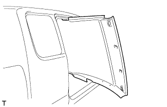
| 31. INSTALL QUARTER PILLAR GARNISH LH (for Extra Cab) |
Attach the 2 clips to install the quarter pillar garnish.
Connect the front seat belt shoulder anchor with the bolt.
- Torque:
- 42 N*m{ 428 kgf*cm , 31 ft.*lbf }
Attach the 4 claws to install the front seat belt shoulder anchor cover.
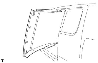
| 32. INSTALL QUARTER PILLAR GARNISH RH (for Extra Cab) |
- HINT:
- Use the same procedure described for the LH side.
| 33. INSTALL INNER UPPER ROOF SIDE GARNISH LH (for Extra Cab) |
Attach the 3 clips to install the inner upper roof side garnish.
w/ Seat Cushion:
Connect the rear seat belt shoulder anchor with the bolt.
- Torque:
- 42 N*m{ 428 kgf*cm , 31 ft.*lbf }
Attach the 2 claws to close the rear seat belt shoulder anchor cover.
| 34. INSTALL INNER UPPER ROOF SIDE GARNISH RH (for Extra Cab) |
- HINT:
- Use the same procedure described for the LH side.
| 35. INSTALL QUARTER INSIDE TRIM BOARD LH (for Extra Cab) |
Attach the 7 clips, 3 guides and 4 claws to install the quarter inside trim board.
Connect the front seat outer belt floor anchor with the bolt.
- Torque:
- 42 N*m{ 428 kgf*cm , 31 ft.*lbf }
| 36. INSTALL QUARTER INSIDE TRIM BOARD RH (for Extra Cab) |
- HINT:
- Use the same procedure described for the LH side.
| 37. INSTALL LOWER BACK PANEL GARNISH (for Extra Cab) |
Attach the 5 clips, 2 guides and 6 claws to install the lower back panel garnish.
| 38. INSTALL UPPER BACK PANEL GARNISH (for Extra Cab) |
Attach the 5 clips and 4 claws to install the upper back panel garnish.
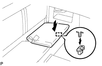
| 39. INSTALL REAR SEAT CUSHION ASSEMBLY LH (for Extra Cab) |
Attach the 2 hooks.
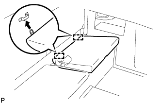 |
Attach the hook to install the rear seat cushion assembly LH.
 |
| 40. INSTALL REAR SEAT CUSHION ASSEMBLY RH (for Extra Cab) |
- HINT:
- Use the same procedures described for the LH side.
| 41. INSTALL FRONT SEAT OUTER BELT ASSEMBLY LH (for Extra Cab) |
|
- NOTICE:
- Do not disassemble the retractor.
w/o Pretensioner single cab and extra cab:
Align the claws with the seat belt positioning holes and install the ELR of the seat belt with the bolt as shown in the illustration.- Torque:
- 42 N*m{ 428 kgf*cm , 31 ft.*lbf }
w/o Pretensioner Double cab:
Align the claws with the seat belt positioning holes and install the ELR of the seat belt with the bolt as shown in the illustration.- Torque:
- 4.8 N*m{ 49 kgf*cm , 42 in.*lbf }
|
w/ Pretensioner:
Install the bolt and seat belt.- Torque:
- 4.8 N*m{ 49 kgf*cm , 42 in.*lbf } for bolt A
- Torque:
- 42 N*m{ 428 kgf*cm , 31 ft.*lbf } for bolt B
|
w/ Pretensioner:
Connect the pretensioner connector as shown in the illustration.
|
Single cab:
Install the anchor with the bolt.- Torque:
- 42 N*m{ 428 kgf*cm , 31 ft.*lbf }
|
Close the cover.
Extra cab and double cab:
Install the anchor with the bolt.- Torque:
- 42 N*m{ 428 kgf*cm , 31 ft.*lbf }
|
Install the cap.
Single cab:
Install the quarter trim panel lower. Then install the seat belt floor anchor with the bolt.- Torque:
- 42 N*m{ 428 kgf*cm , 31 ft.*lbf }
|
Extra cab:
Install the quarter inside trim board. Then install the seat belt floor anchor with the bolt.- Torque:
- 42 N*m{ 428 kgf*cm , 31 ft.*lbf }
|
Double cab:
Install the anchor of the seat belt with the built-in bolt after installing the center pillar garnish lower.- Torque:
- 42 N*m{ 428 kgf*cm , 31 ft.*lbf }
|
| 42. INSTALL FRONT SEAT OUTER BELT ASSEMBLY RH (for Extra Cab) |
|
- NOTICE:
- Do not disassemble the retractor.
w/o Pretensioner single cab and extra cab:
Align the claws with the seat belt positioning holes and install the ELR of the seat belt with the bolt as shown in the illustration.- Torque:
- 42 N*m{ 428 kgf*cm , 31 ft.*lbf }
w/o Pretensioner Double cab:
Align the claws with the seat belt positioning holes and install the ELR of the seat belt with the bolt as shown in the illustration.- Torque:
- 4.8 N*m{ 49 kgf*cm , 42 in.*lbf }
|
w/ Pretensioner:
Install the bolt and seat belt.- Torque:
- 4.8 N*m{ 49 kgf*cm , 42 in.*lbf } for bolt A
- Torque:
- 42 N*m{ 428 kgf*cm , 31 ft.*lbf } for bolt B
|
w/ Pretensioner:
Connect the pretensioner connector as shown in the illustration.
|
Single cab:
Install the anchor with the bolt.- Torque:
- 42 N*m{ 428 kgf*cm , 31 ft.*lbf }
|
Close the cover.
Extra cab and double cab:
Install the anchor with the bolt.- Torque:
- 42 N*m{ 428 kgf*cm , 31 ft.*lbf }
|
Install the cap.
Single cab:
Install the quarter trim panel lower. Then install the seat belt floor anchor with the bolt.- Torque:
- 42 N*m{ 428 kgf*cm , 31 ft.*lbf }
|
Extra cab:
Install the quarter inside trim board. Then install the seat belt floor anchor with the bolt.- Torque:
- 42 N*m{ 428 kgf*cm , 31 ft.*lbf }
|
Double cab:
Install the anchor of the seat belt with the built-in bolt after installing the center pillar garnish lower.- Torque:
- 42 N*m{ 428 kgf*cm , 31 ft.*lbf }
|
| 43. INSTALL FRONT DOOR OPENING TRIM LH (for Extra Cab) |
 |
Align the paint mark on the front door opening trim with the mark position on the vehicle and install the front door opening trim as shown in the illustration.
Text in Illustration *1 Paint Mark *2 Mark Position
| 44. INSTALL FRONT DOOR OPENING TRIM RH (for Extra Cab) |
- HINT:
- Use the same procedure described for the LH side.
| 45. INSTALL FRONT DOOR SCUFF PLATE RH (for Extra Cab) |
Attach the 4 clips and 8 claws to install the front door scuff plate.
| 46. INSTALL FRONT DOOR SCUFF PLATE RH (for Extra Cab) |
- HINT:
- Use the same procedure described for the LH side.
| 47. INSTALL ROOF HEADLINING ASSEMBLY (for Double Cab) |
for LHD:
Place the roof headlining into the vehicle as shown in the illustration.
- NOTICE:
- Be careful not to damage the roof headlining when placing it.
Install the roof headlining with the clips.
Text in Illustration *A w/o Assist Grip Connect the connectors and attach the 4 clamps.
for RHD:
Place the roof headlining into the vehicle as shown in the illustration.
- NOTICE:
- Be careful not to damage the roof headlining when placing it.
Install the roof headlining with the clips.
Connect the connectors and attach the 5 clamps.
Text in Illustration *A w/o Assist Grip
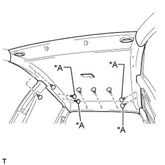
Attach the 5 clamps to the front pillar.
| 48. INSTALL ASSIST GRIP (for Double Cab) |
- HINT:
- Use the same procedure for all assist grips.
Install the assist grip with the 2 screws.
Install the screw.
| 49. INSTALL QUARTER INSIDE TRIM BOARD RH (for Double Cab) |
Attach the 4 clips to install the quarter inside trim board.
Connect the rear seat belt shoulder anchor with the bolt.
- Torque:
- 42 N*m{ 428 kgf*cm , 31 ft.*lbf }
Attach the 2 claws to close the rear seat belt shoulder anchor cover.
| 50. INSTALL QUARTER INSIDE TRIM BOARD RH (for Double Cab) |
- HINT:
- Use the same procedure described for the LH side.
| 51. INSTALL LOWER QUARTER TRIM PANEL LH (for Double Cab) |
Attach the 3 clips and claw to install the lower quarter trim panel.
| 52. INSTALL LOWER QUARTER TRIM PANEL RH (for Double Cab) |
- HINT:
- Use the same procedure described for the LH side.
| 53. INSTALL REAR NO. 1 SEAT OUTER BELT ASSEMBLY LH (for Double Cab) |
 |
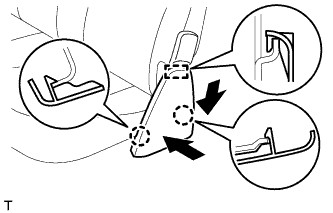
Align the claws with the seat belt positioning holes and install the ELR of the seat belt with the bolt as shown in the illustration.
- Torque:
- 42 N*m{ 428 kgf*cm , 31 ft.*lbf } for bolt A
- Torque:
- 4.8 N*m{ 49 kgf*cm , 42 in.*lbf } for bolt B
Install the bolt and close the cover as shown in the illustration.
- Torque:
- 42 N*m{ 428 kgf*cm , 31 ft.*lbf }
 |
Install the floor anchor with the bolt, as shown in the illustration.
- Torque:
- 42 N*m{ 428 kgf*cm , 31 ft.*lbf }
 |
Install the floor anchor with the bolt, as shown in the illustration.
- Torque:
- 42 N*m{ 428 kgf*cm , 31 ft.*lbf }
 |
| 54. INSTALL REAR NO. 1 SEAT OUTER BELT ASSEMBLY RH (for Double Cab) |
|
Align the claws with the seat belt positioning holes and install the ELR of the seat belt with the bolt as shown in the illustration.
- Torque:
- 42 N*m{ 428 kgf*cm , 31 ft.*lbf } for bolt A
- Torque:
- 4.8 N*m{ 49 kgf*cm , 42 in.*lbf } for bolt B
Install the bolt and close the cover as shown in the illustration.
- Torque:
- 42 N*m{ 428 kgf*cm , 31 ft.*lbf }
|
Install the floor anchor with the bolt, as shown in the illustration.
- Torque:
- 42 N*m{ 428 kgf*cm , 31 ft.*lbf }
|
Install the floor anchor with the bolt, as shown in the illustration.
- Torque:
- 42 N*m{ 428 kgf*cm , 31 ft.*lbf }
|
| 55. INSTALL REAR DOOR OPENING TRIM LH (for Double Cab) |
 |
Align the paint mark on the rear door opening trim with the mark position on the vehicle and install the rear door opening trim as shown in the illustration.
Text in Illustration *1 Paint Mark *2 Mark Position
| 56. INSTALL REAR DOOR OPENING TRIM RH (for Double Cab) |
- HINT:
- Use the same procedure described for the LH side.
| 57. INSTALL REAR DOOR SCUFF PLATE LH (for Double Cab) |
Attach the 2 clips and 7 claws to install the rear door scuff plate.
| 58. INSTALL REAR DOOR SCUFF PLATE RH (for Double Cab) |
- HINT:
- Use the same procedure described for the LH side.
| 59. INSTALL UPPER BACK PANEL GARNISH (for Double Cab) |
Attach the 5 clips and 4 claws to install the upper back panel garnish.
| 60. INSTALL REAR SEAT ASSEMBLY (for Double Cab) |
Install rear seat assembly (Click here).
| 61. INSTALL REAR SEAT HINGE COVER LH (for Double Cab) |
Attach the guide.
 |
Push the rear seat hinge cover LH to attach the 2 claws and install the rear seat hinge cover LH.
| 62. INSTALL REAR SEAT HINGE COVER RH (for Double Cab) |
- HINT:
- Use the same procedures described for the LH side.
| 63. CHECK FOR LEAKS AND REPAIR |
Conduct a leak test after the adhesive has completely hardened.
Seal any leaks with auto glass sealer.
| 64. CONNECT CABLE TO NEGATIVE BATTERY TERMINAL |
| 65. PERFORM INITIALIZATION |
Perform initialization (Click here).
- NOTICE:
- Certain systems need to be initialized after disconnecting and reconnecting the cable from the negative (-) battery terminal.