AUDIO AND VISUAL SYSTEM (for Radio and Display Type) > Steering Pad Switch Circuit |

for Preparation Click here
DESCRIPTION
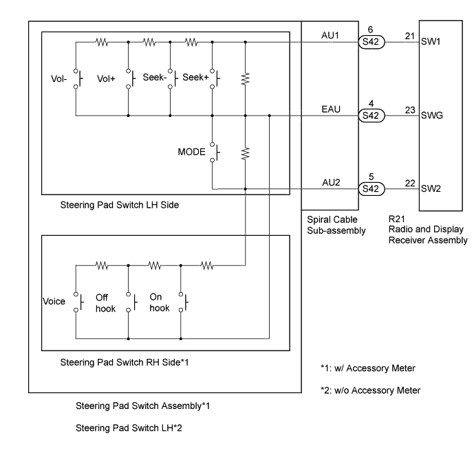
- *1: w/ Accessory Meter
- *2: w/o Accessory Meter
If there is an open in the circuit, the audio system cannot be operated using the steering pad switch assembly*1 or steering pad switch LH*2.
If there is a short in the circuit, the same condition as when the switch is continuously depressed occurs.
Therefore, the radio and display receiver assembly cannot be operated using the steering pad switch assembly*1 or steering pad switch LH*2, and the radio and display receiver assembly itself cannot function.
WIRING DIAGRAM
INSPECTION PROCEDURE
- CAUTION:
- The vehicle is equipped with an SRS (Supplemental Restraint System) which includes components such as airbags. Before servicing (including removal or installation of parts), be sure to read the precautionary notice for the SRS (Click here).
| 1.INSPECT STEERING PAD SWITCH |
- *1: w/ Accessory Meter
- *2: w/o Accessory Meter
Remove the steering pad switch assembly*1 or steering pad switch LH*2 (Click here).
Inspect the steering pad switch assembly*1 or steering pad switch LH*2 (Click here).
|
| ||||
| OK | |
| 2.INSPECT SPIRAL CABLE SUB-ASSEMBLY |
Remove the spiral cable sub-assembly (Click here).
Inspect the spiral cable sub-assembly (Click here).
|
| ||||
| OK | |
| 3.CHECK HARNESS AND CONNECTOR (RADIO AND DISPLAY RECEIVER ASSEMBLY - SPIRAL CABLE SUB-ASSEMBLY) |
Disconnect the R21 radio and display receiver assembly connector.
Disconnect the S42 spiral cable sub-assembly connector.
Measure the resistance according to the value(s) in the table below.
- Standard Resistance:
Tester Connection Condition Specified Condition R21-21 (SW1) - S42-6 (AU1) Always Below 1 Ω R21-22 (SW2) - S42-5 (AU2) R21-23 (SWG) - S42-4 (EAU) R21-21 (SW1) - Body ground Always 10 kΩ or higher R21-22 (SW2) - Body ground R21-23 (SWG) - Body ground
|
| ||||
| OK | ||
| ||