AIR CONDITIONING SYSTEM (for Automatic Air Conditioning System) > Vehicle Speed Signal Circuit |

for Preparation Click here
DESCRIPTION
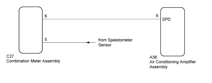
The air conditioning amplifier assembly monitors signals from the speedometer sensor via the combination meter assembly. The air conditioning amplifier assembly uses these signals to adjust the thermistor signal.WIRING DIAGRAM
INSPECTION PROCEDURE
- HINT:
- Check that the speedometer in the combination meter assembly operates normally before inspecting the vehicle speed signal circuit (Click here).
| 1.CHECK AIR CONDITIONING AMPLIFIER ASSEMBLY |
Remove the air conditioning amplifier assembly with its connectors still connected (Click here).
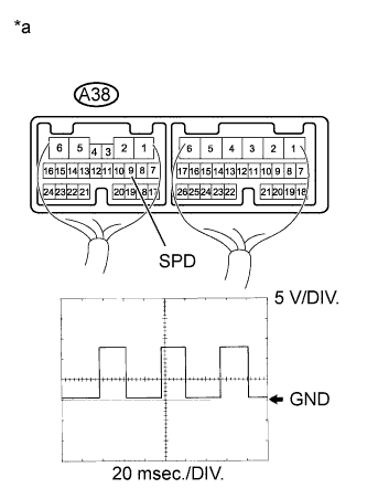 |
Using an oscilloscope, check the waveform of the air conditioning amplifier assembly.
Measurement Condition Item Content Tester Connection A38-9 (SPD) - Body ground Tool Setting 5 V/DIV., 20 ms./DIV. Condition Driving at approximately 20 km/h (12 mph) - OK:
- Waveform is as shown in the illustration.
Text in Illustration *a Component with harness connected
(Air Conditioning Amplifier Assembly)- HINT:
- As the vehicle speed increases, the wavelength becomes shorter.
|
| ||||
| OK | ||
| ||
| 2.CHECK COMBINATION METER ASSEMBLY |
Remove the combination meter assembly with its connector still connected (Click here).
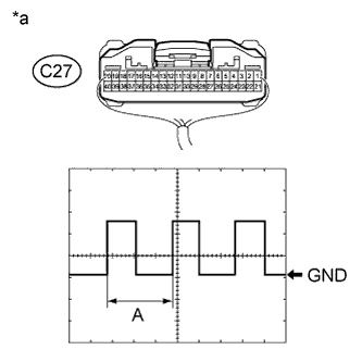 |
Connect an oscilloscope to the combination meter assembly connector.
Check the waveform.
Measurement Condition Item Content Tester Connection C27-6 - Body ground Tool setting 5 V/DIV., 20 ms./DIV. Condition Vehicle is driven at approximately 20 km/h (12 mph) - OK:
- Waveform is as shown in the illustration.
Text in Illustration *a Component with harness connected
(Combination Meter Assembly)- HINT:
- When the system is functioning normally, one wheel revolution generates 4 pulses. As the vehicle speed increases, the width indicated by (A) in the illustration narrows.
|
| ||||
| OK | |
| 3.CHECK HARNESS AND CONNECTOR (COMBINATION METER - AIR CONDITIONING AMPLIFIER) |
Disconnect the C27 combination meter assembly connector.
Disconnect the A38 air conditioning amplifier assembly connector.
Measure the resistance according to the value(s) in the table below.
- Standard Resistance:
Tester Connection Condition Specified Condition C27-6 - A38-9 (SPD) Always Below 1 Ω A38-9 (SPD) - Body ground Always 10 kΩ or higher
|
| ||||
| OK | ||
| ||