AUDIO AND VISUAL SYSTEM (for Radio and Display Type) > Radio Receiver Power Source Circuit |

for Preparation Click here
DESCRIPTION
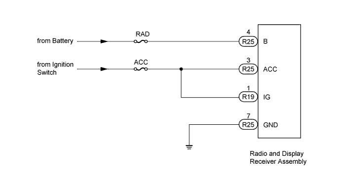
This circuit provides power to the radio and display receiver assembly.WIRING DIAGRAM
INSPECTION PROCEDURE
- NOTICE:
- Inspect the fuses for circuits related to this system before performing the following inspection procedure.
| 1.CHECK HARNESS AND CONNECTOR (RADIO AND DISPLAY RECEIVER - BATTERY AND BODY GROUND) |
Disconnect the R25 and R19 radio and display receiver assembly connectors.
 |
Measure the resistance according to the value(s) in the table below.
- Standard Resistance:
Tester Connection Condition Specified Condition R25-7 (GND) - Body ground Always Below 1 Ω
Measure the voltage according to the value(s) in the table below.
- Standard Voltage:
Tester Connection Condition Specified Condition R25-4 (B) - Body ground Always 11 to 14 V R25-3 (ACC) - Body ground Ignition switch ACC R19-1 (IG) - Body ground Ignition switch ON
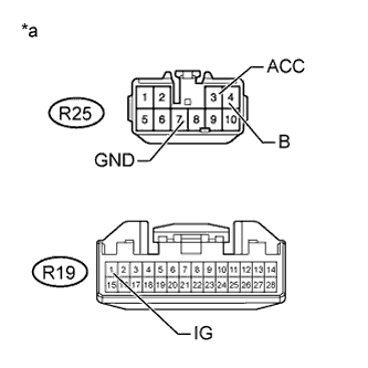
| *a | Front view of wire harness connector (to Radio and Display Receiver Assembly) |
|
| ||||
| OK | ||
| ||