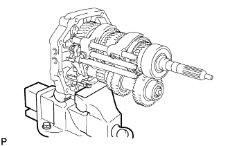
MANUAL TRANSMISSION UNIT > REMOVAL |

for Preparation Click here
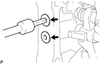
| 1. REMOVE FILLER PLUG |
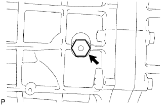 |
Remove the filler plug and gasket from the transmission case.
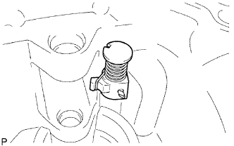
| 2. REMOVE DRAIN PLUG |
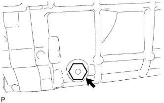 |
Remove the drain plug and gasket from the transmission case.
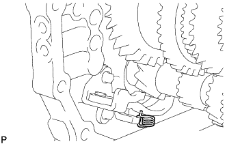
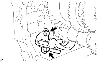
| 3. REMOVE CLUTCH RELEASE FORK SUB-ASSEMBLY |
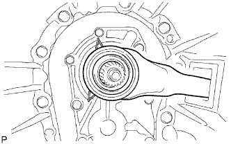 |
Remove the release fork and release bearing from the clutch housing.
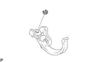
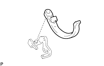
| 4. REMOVE CLUTCH RELEASE BEARING ASSEMBLY |
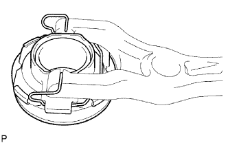 |
Remove the clip and then remove the release bearing from the release fork.
| 5. REMOVE RELEASE FORK SUPPORT |
 |
Remove the release fork support from the clutch housing.
| 6. REMOVE CLUTCH RELEASE FORK BOOT |
 |
Remove the release fork boot from the clutch housing.
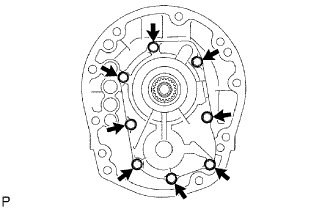
| 7. REMOVE CLUTCH HOUSING |
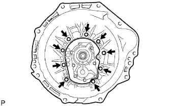 |
Remove the 9 bolts.
Using a plastic-faced hammer, tap out the clutch housing from the transmission case.
 |
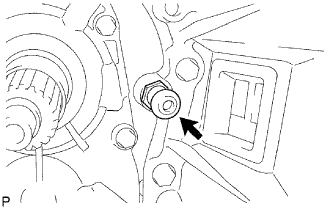
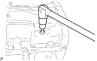
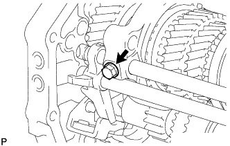
| 8. REMOVE BACK-UP LIGHT SWITCH ASSEMBLY |
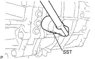 |
Using SST, remove the back-up light switch and gasket from the transmission case.
- SST
- 09817-16011
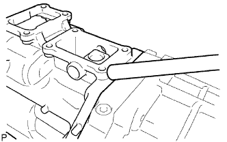
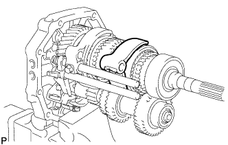
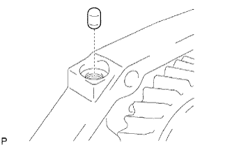
| 9. REMOVE RESTRICT PIN |
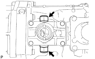 |
Remove the 2 restrict pins from the transfer adapter.
| 10. REMOVE CONTROL SHIFT LEVER RETAINER |
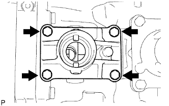 |
Remove the 4 bolts.
Remove the control shift lever retainer.
Remove the oil deflector.
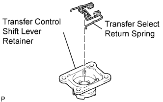
| 11. REMOVE TRANSFER CONTROL SHIFT LEVER RETAINER |
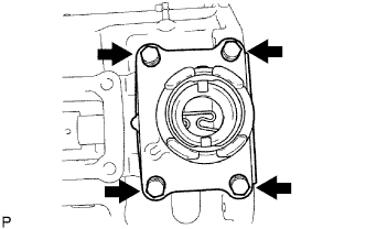 |
Remove the 4 bolts.
Remove the shift lever retainer from the transfer adapter.
Remove the select return spring from the shift lever retainer.
 |
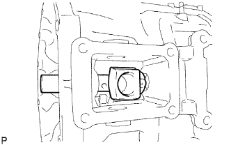
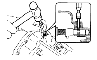
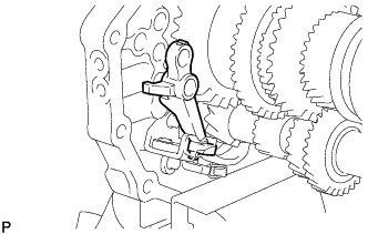
| 12. REMOVE SHIFT AND SELECT LEVER SHAFT |
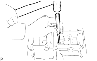 |
Using a 5 mm pin punch and hammer, tap out the slotted spring pin from the shift lever housing.
Remove the shift and select lever shaft and shift lever housing from the transfer adapter.
 |
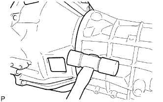
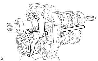
| 13. REMOVE TRANSFER ADAPTER |
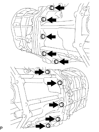 |
Remove the 10 bolts.
Using a brass bar and hammer, tap out the transfer adapter from the transmission case.
 |
| 14. REMOVE OIL RECEIVER PIPE |
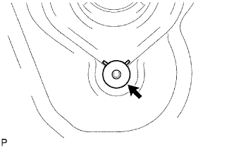 |
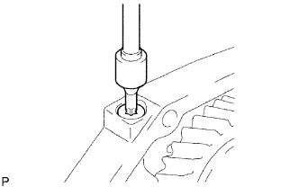
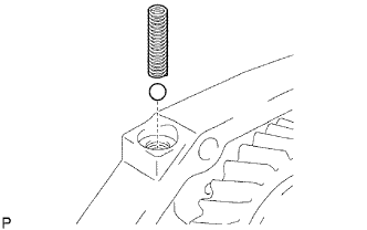
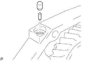
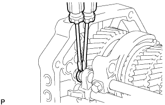
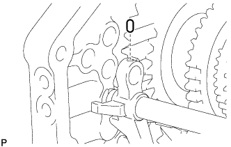
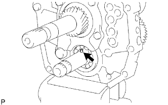
| 15. REMOVE REVERSE RESTRICT PIN |
 |
Using a T40 ''torx'' socket wrench, remove the plug.
Using a 5 mm pin punch and hammer, tap out the restrict slotted pin.
 |
Remove the restrict pin.
 |
| 16. REMOVE TRANSFER ADAPTER OIL SEAL |
 |
Using a screwdriver and hammer, tap out the oil seal from the transfer adapter.
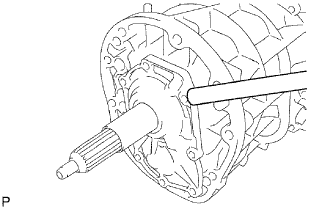
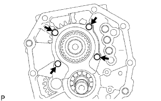
| 17. REMOVE FRONT BEARING RETAINER |
 |
Remove the 8 bolts.
Using a brass bar and hammer, tap out the retainer from the transmission case.
 |
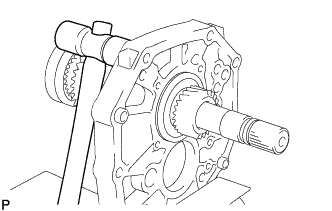
| 18. REMOVE TRANSMISSION FRONT BEARING RETAINER OIL SEAL |
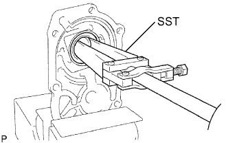 |
Fix the front bearing retainer in a vise.
Using SST, tap out the oil seal.
- SST
- 09308-00010
| 19. REMOVE FRONT BEARING SHAFT SNAP RING |
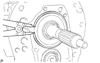 |
Using a snap ring expander, remove the snap ring from the transmission case.
| 20. REMOVE NO. 1 COUNTER GEAR FRONT BEARING SNAP RING |
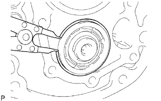 |
Using a snap ring expander, remove the snap ring from the transmission case.
| 21. REMOVE MANUAL TRANSMISSION CASE |
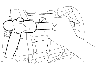 |
Using a brass bar and hammer, tap out the transmission case from the intermediate plate.
| 22. REMOVE TRANSMISSION MAGNET |
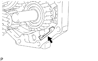 |
Remove the magnet from the intermediate plate.
| 23. FIX INTERMEDIATE PLATE |
 |
Fix the intermediate plate in a vise between aluminum plates.
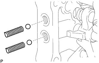
| 24. REMOVE NO. 1 SHIFT DETENT BALL SPRING SEAT |
 |
Using a T40 ''torx'' socket wrench, remove the spring seat from the intermediate plate.
Using a magnet hand, remove the compression spring and detent ball from the intermediate plate.
 |
Using a T40 ''torx'' socket wrench, remove the 2 spring seats from the intermediate plate.
 |
Using a magnet hand, remove the 2 compression springs and 2 detent balls from the intermediate plate.
 |
| 25. REMOVE NO. 2 SHIFT FORK SHAFT |
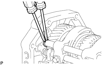 |
Using 2 screwdrivers and a hammer, tap out the snap ring from the No. 2 shift fork shaft.
- NOTICE:
- Use a cloth to prevent the snap ring from flying off.
Remove the bolt from the No. 2 shift fork.
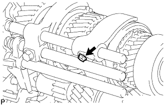 |
Remove the No. 2 shift fork shaft from the intermediate plate.
 |
Remove the No. 2 shift fork from the No. 2 transmission hub sleeve.
 |
Using a magnet hand, remove the No. 1 shift interlock roller and shift interlock pin from the intermediate plate.
 |
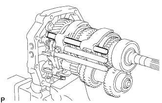
| 26. REMOVE NO. 1 SHIFT FORK SHAFT |
 |
Using 2 screwdrivers and a hammer, tap out the snap ring from the No. 1 shift fork shaft.
- NOTICE:
- Use a cloth to prevent the snap ring from flying off.
Remove the bolt from the No. 1 shift fork.
 |
Remove the No. 1 shift fork shaft from the intermediate plate.
 |
Remove the No. 1 shift fork from the reverse gear.
 |
Using a magnet hand, remove the No. 1 shift interlock roller from the intermediate plate.
 |
| 27. REMOVE NO. 3 SHIFT FORK SHAFT |
 |
Using a 5 mm pin punch and hammer, tap out the shift fork set slotted pin from the No. 3 shift fork.
Using 2 screwdrivers and a hammer, tap out the snap ring from the shift fork shaft.
- NOTICE:
- Use a cloth to prevent the snap ring from flying off.
 |
Using a magnet hand, remove the straight pin from the reverse shift fork.
 |
Remove the No. 3 shift fork and No. 3 shift fork shaft from the intermediate plate.
 |
Using a magnet hand, remove the No. 1 shift interlock roller from the intermediate plate.
 |
| 28. REMOVE REVERSE SHIFT FORK |
Remove the reverse shift fork from the reverse shift arm.
 |
| 29. REMOVE REVERSE SHIFT ARM BRACKET |
Remove the torsion spring from the reverse shift arm bracket.
 |
Remove the 2 bolts and reverse shift arm bracket from the intermediate plate.
 |
Using a screwdriver, pry out the snap ring from the reverse shift arm bracket.
 |
Remove the reverse shift arm from the reverse shift arm bracket.
 |
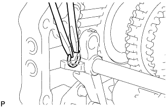
| 30. REMOVE OUTPUT SHAFT BEARING SHAFT SNAP RING |
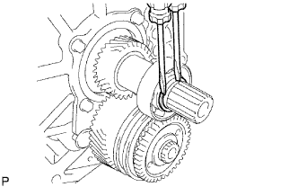 |
Using 2 screwdrivers and a hammer, tap out the shaft snap ring from the output shaft.
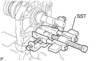
| 31. REMOVE OUTPUT SHAFT REAR BEARING |
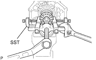 |
Using SST, remove the rear bearing and output shaft spacer from the output shaft.
- SST
- 09950-40011
(09951-04010, 09952-04010, 09953-04020, 09954-04010, 09955-04051, 09957-04010, 09958-04011)
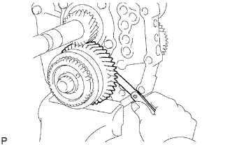
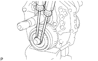
| 32. INSPECT COUNTER 5TH GEAR CLEARANCE |
Using a feeler gauge, measure the thrust clearance.
- Standard clearance:
- 0.10 to 0.35 mm (0.0039 to 0.0138 in.)
 |
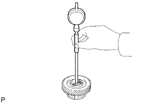
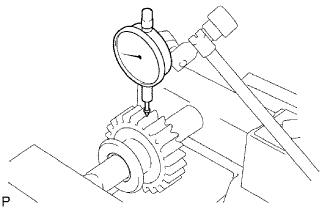
| 33. INSPECT COUNTER 5TH GEAR RADIAL CLEARANCE |
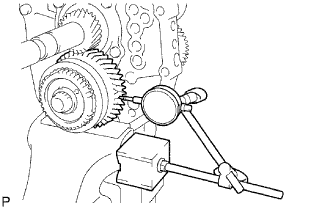 |
Using a dial indicator, measure the radial clearance.
- Standard clearance:
- 0.015 to 0.068 mm (0.0059 to 0.0027 in.)
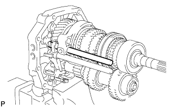
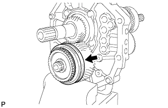
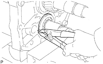
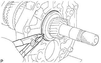
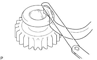
| 34. REMOVE COUNTER GEAR REAR SHAFT SNAP RING |
 |
Using 2 screwdrivers and a hammer, tap out the snap ring from the counter gear.
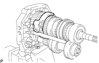
| 35. REMOVE NO. 3 TRANSMISSION HUB SLEEVE |
Remove the No. 3 transmission hub sleeve from the counter 5th gear.
 |
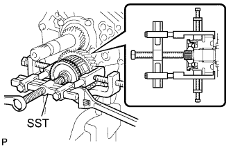
| 36. REMOVE COUNTER 5TH GEAR |
Using SST, remove the counter 5th gear together with the 2 No. 3 synchromesh shifting keys, 2 No. 3 synchromesh shifting key springs, No. 3 synchronizer ring and No. 5 gear spring piece from the counter gear.
- SST
- 09950-40011
(09951-04020, 09952-04010, 09953-04020, 09954-04010, 09955-04021, 09957-04010, 09958-04011)
 |
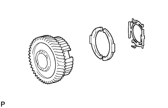
| 37. REMOVE NO. 5 GEAR SPRING PIECE |
Remove the No. 5 gear spring piece from the counter 5th gear.
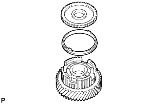 |
| 38. REMOVE NO. 3 SYNCHRONIZER RING |
Remove the synchronizer ring from the counter 5th gear.
| 39. REMOVE COUNTER 5TH GEAR BEARING |
Remove the bearing from the counter 5th gear.
 |
| 40. REMOVE NO. 3 SYNCHROMESH SHIFTING KEY |
Using a snap ring expander, remove the snap ring.
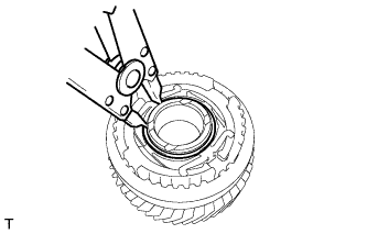 |
Remove the No. 3 synchromesh shifting key spring and 2 No. 3 synchromesh shifting keys from the counter 5th gear.
 |
| 41. REMOVE 5TH GEAR THRUST WASHER |
 |
Remove the thrust washer from the counter gear.
| 42. REMOVE 5TH GEAR THRUST WASHER PIN |
 |
Remove the thrust washer pin from the counter gear.
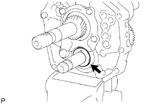
| 43. REMOVE REAR BEARING RETAINER |
 |
Remove the 4 bolts and bearing retainer from the intermediate plate.
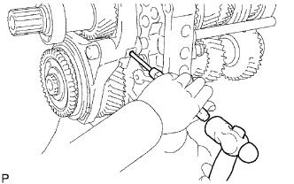
| 44. REMOVE REVERSE IDLER GEAR |
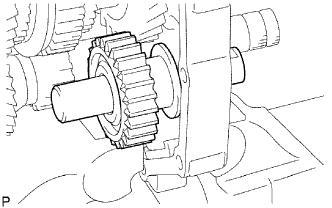 |
Pull out the reverse idler gear shaft to the rear side and remove the reverse idler gear from the intermediate plate.
| 45. REMOVE COUNTER SHAFT CENTER BEARING |
 |
Using a snap ring expander, remove the snap ring.
Using SST, remove the center bearing from the intermediate plate.
- SST
- 09950-40011
(09951-04010, 09952-04010, 09953-04020, 09954-04010, 09955-04011, 09957-04010, 09958-04011)
- HINT:
- Remove the bearing while tapping the tip of the counter gear so that the counter gear does not hit the side wall of the output shaft gear by being pushed forward.
 |
| 46. REMOVE COUNTER GEAR |
 |
Remove the counter gear from the intermediate plate.
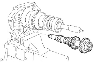
| 47. REMOVE INPUT SHAFT ASSEMBLY |
 |
Remove the input shaft and No. 2 synchronizer ring from the output shaft.
- NOTICE:
- Do not drop the input shaft bearing and the No. 2 synchronizer ring.
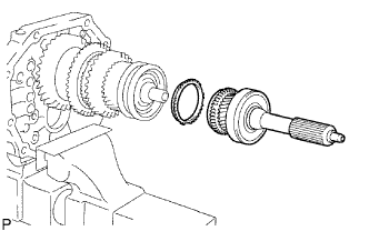
| 48. REMOVE OUTPUT SHAFT BEARING SHAFT SNAP RING |
 |
Using a snap ring expander, remove the snap ring from the output shaft.
| 49. REMOVE OUTPUT SHAFT ASSEMBLY |
 |
Using a plastic-faced hammer, remove the output shaft by tapping the intermediate plate.
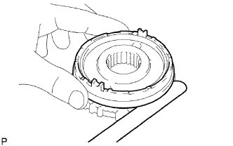
| 50. INSPECT NO. 3 SYNCHRONIZER RING |
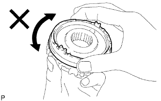 |
Apply gear oil to the cone part of the No. 5 gear spline piece, and check that it does not turn in both directions while pushing the No. 3 synchronizer ring to the No. 5 gear spline piece.
If it can turn, replace the No. 3 synchronizer ring.
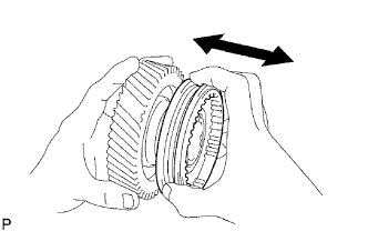
Push the No. 3 synchronizer ring outer to the cone part of the No. 5 gear spline piece. Measure the clearance between the No. 3 synchronizer ring outer and No. 5 gear spline piece.
- Standard clearance:
- 0.68 to 1.32 mm (0.0268 to 0.0519 in.)
 |
| 51. INSPECT NO. 3 TRANSMISSION HUB SLEEVE |
 |
Check the sliding condition between the counter shaft 5th gear and No. 3 transmission hub sleeve.
Check the tip of the spline gear of the No. 3 transmission hub sleeve for wear.
If there are any defects, replace the No. 3 transmission hub sleeve.
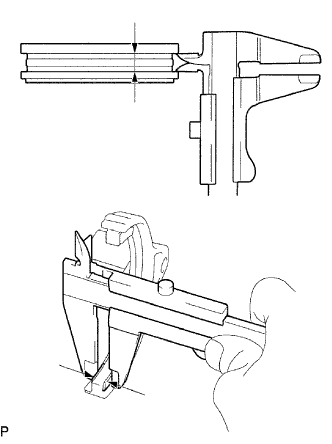
Using a vernier caliper, measure the No. 3 transmission hub sleeve groove and the thickness of the claw part of the No. 3 shift fork to calculate the clearance.
- Standard clearance:
- 0.26 to 0.84 mm (0.0102 to 0.0331 in.)
 |
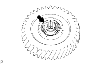
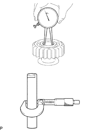
| 52. INSPECT COUNTER 5TH GEAR |
 |
Using a cylinder gauge, measure the inside diameter of the counter 5th gear.
- Standard inside diameter:
- 38.015 to 38.040 mm (1.4967 to 1.4976 in.)
- Maximum inside diameter:
- 38.040 mm (1.4976 in.)
| 53. INSPECT REVERSE IDLER GEAR SUB-ASSEMBLY |
 |
Using a caliper gauge, measure the inside diameter of the reverse idler gear.
- Standard inside diameter:
- 24.040 to 24.061 mm (0.9465 to 0.9473 in.)
- Maximum inside diameter:
- 24.061 mm (0.9473 in.)
Using a micrometer, measure the diameter of the sliding part of the reverse idler gear on the reverse idler gear shaft.
- Standard diameter:
- 23.979 to 24.000 mm (0.9441 to 0.9449 in.)
- Minimum diameter:
- 23.979 mm (0.9441 in.)
Using a feeler gauge, measure the thrust clearance of the shoe part between the reverse idler gear and reverse shift arm.
- Standard clearance:
- 0.05 to 0.35 mm (0.0020 to 0.0138 in.)
 |
| 54. INSPECT REVERSE IDLER GEAR RADIAL CLEARANCE |
 |
Install the reverse idler gear on the reverse idler gear shaft, and clamp it to a vise.
Using a dial indicator, measure the radical clearance.
- Standard clearance:
- 0.040 to 0.082 mm (0.0016 to 0.0032 in.)