ANTI-LOCK BRAKE SYSTEM (w/ Rear Differential Lock) > TS and CG Terminal Circuit |

for Preparation Click here
DESCRIPTION
If the vehicle is stationary during sensor check mode, speed sensor malfunctions cannot be detected. The vehicle must be driven for speed sensor malfunctions to be detected.- HINT:
- Change to sensor check mode by connecting terminals TC and CG of the DLC3, and turning the ignition switch from OFF to ON.
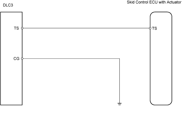
WIRING DIAGRAM
INSPECTION PROCEDURE
| 1.CHECK WIRE HARNESS (DLC3 - SKID CONTROL ECU AND BODY GROUND) |
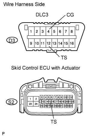 |
Disconnect the S2 ECU connector.
Measure the resistance of the wire harness side connectors.
- Standard resistance:
Tester Connection Specified Condition D3-4 (CG) - Body ground Below 1 Ω D3-12 (TS) - S2-15 (TS) Below 1 Ω S2-15 (TS) - Body ground 10 kΩ or higher
|
| ||||
| OK | ||
| ||