DTC P0500 Vehicle Speed Sensor "A" |

for Preparation Click here
DESCRIPTION
The speed sensors detect the wheel speed and send the appropriate signals to the skid control ECU. The skid control ECU converts these wheel speed signals into a 4-pulse signal and outputs it to the ECM via the combination meter. The ECM determines the vehicle speed based on the frequency of these pulse signals.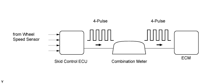
| DTC No. | DTC Detection Condition | Trouble Area |
| P0500 | While vehicle being driven, no vehicle speed sensor signal transmitted to ECM (2 trip detection logic: Manual transaxle models) (1 trip detection logic: Automatic transaxle models) |
|
MONITOR DESCRIPTION
Automatic Transaxle Models:The ECM assumes that the vehicle is being driven when the vehicle speed sensor signal is being transmitted by the combination meter. If there is no signal from the combination meter, despite the ECM detecting the speed signal from the speed sensor, the ECM interprets this as a malfunction in the speed signal circuit. The ECM then illuminates the MIL and stores the DTC.
Manual Transaxle Models:
The ECM assumes that the vehicle is being driven when the idle fuel-cut operation* is being executed. If there is no signal from the vehicle speed sensor despite this conditions being met, the ECM interprets this as a malfunction in the speed signal circuit. The ECM then illuminates the MIL and stores the DTC.
*: Idle fuel-cut is executed when the throttle valve is fully closed and engine speed is over 2500 rpm.
MONITOR STRATEGY
| Related DTCs | P0500: Vehicle speed sensor verify pulse input |
| Required Sensors/Components (Main) | Vehicle speed sensor Combination meter Skid control ECU |
| Required Sensors/Components (Related) | Park/neutral position switch Engine coolant temperature sensor Crankshaft position sensor Throttle position sensor Mass air flow meter |
| Frequency of Operation | Continuous |
| Duration | 2 seconds: Automatic transaxle models 4.7 seconds: Manual transaxle models |
| MIL Operation | Immediate: Automatic transaxle models 2 driving cycles: Manual transaxle models |
| Sequence of Operation | None |
TYPICAL ENABLING CONDITIONS
| Monitor runs whenever following DTCs are not present | None |
| Time after ignition switch off to ON | 3 seconds or more |
| Starter | Off |
| Battery voltage | 8 V or more |
| Idle | On |
| Fuel cut | On |
| Monitor runs whenever following DTCs are not present | None |
| Time after ignition switch off to ON | 3 seconds or more |
| Battery voltage | 8 V or more |
| Ignition switch | ON |
| Starter | Off |
| Engine | Running |
| Transmission counter gear revolution | 300 rpm or more |
| Either of the following conditions is met | Condition A or B |
| A. All of the following conditions are met | - |
| Engine coolant temperature | 20°C (68°F) or higher |
| Engine coolant temperature sensor fail (P0115, P0117, P0118, P0125) | Not detected |
| Time after park/neutral position switch turned from on to off | 2 seconds or more |
| B. Both of the following conditions are met | Conditions 1 and 2 |
| 1. Either of the following conditions is met | Condition (a) and (b) |
| (a) Engine coolant temperature | Below 20°C (68°F) |
| (b) Engine coolant temperature sensor fail (P0115, P0117, P0118, P0125) | Detected |
| 2. Time after park/neutral position switch turned from on to off | 30 seconds or more |
TYPICAL MALFUNCTION THRESHOLDS
| Vehicle speed sensor signal | No signal |
CONFIRMATION DRIVING PATTERN
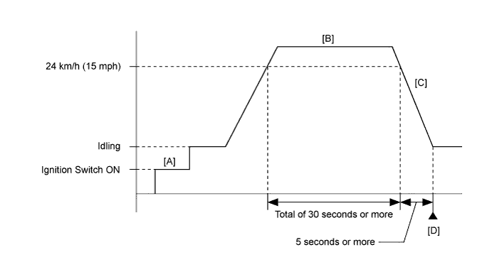
- Connect the Techstream to the DLC3.
- Turn the ignition switch to ON and turn the Techstream on.
- Clear the DTCs (even if no DTCs are stored, perform the clear DTC procedure) (Click here).
- Turn the ignition switch off and wait for at least 30 seconds.
- Turn the ignition switch to ON and turn the Techstream on [A].
- Start the engine.
- Enter the following menus to check the fuel-cut status: Powertrain / Engine and ECT / Data List / Idle Fuel Cut.
- Drive the vehicle at 15 mph (24 km/h) or more for a total of 30 seconds or more [B].
- CAUTION:
- When performing the confirmation driving pattern, obey all speed limits and traffic laws.
- Decelerate the vehicle by releasing the accelerator pedal for 5 seconds or more to perform the fuel-cut [C].
- Stop the vehicle.
- Enter the following menus: Powertrain / Engine and ECT / Trouble Codes [D].
- Read the pending DTCs.
- HINT:
- If a pending DTC is output, the system is malfunctioning.
- If a pending DTC is not output, perform the following procedure.
- Enter the following menus: Powertrain / Engine and ECT / Utility / All Readiness.
- Input the DTC: P0500.
- Check the DTC judgment result.
Techstream Display Description NORMAL - DTC judgment completed
- System normal
ABNORMAL - DTC judgment completed
- System abnormal
INCOMPLETE - DTC judgment not completed
- Perform driving pattern after confirming DTC enabling conditions
N/A - Unable to perform DTC judgment
- Number of DTCs which do not fulfill DTC preconditions has reached ECU memory limit
- HINT:
- If the judgment result shows NORMAL, the system is normal.
- If the judgment result shows ABNORMAL, the system has a malfunction.
- DTC judgment completed
- If the judgment result is INCOMPLETE or N/A and no pending DTC is output, perform a universal trip and check for permanent DTCs (Click here).
- HINT:
- If a permanent DTC is output, the system is malfunctioning.
- If no permanent DTC is output, the system is normal.
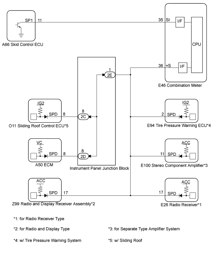
WIRING DIAGRAM
INSPECTION PROCEDURE
- HINT:
- Read freeze frame data using the Techstream. The ECM records vehicle and driving condition information as freeze frame data the moment a DTC is stored. When troubleshooting, freeze frame data can be helpful in determining whether the vehicle was running or stopped, whether the engine was warmed up or not, whether the air fuel ratio was lean or rich, as well as other data recorded at the time of a malfunction.
| 1.READ VALUE USING TECHSTREAM (VEHICLE SPEED) |
Connect the Techstream to the DLC3.
Turn the ignition switch to ON.
Turn the Techstream on.
Enter the following menus: Powertrain / Engine and ECT / Data List / Vehicle Speed.
Drive the vehicle.
Read the value displayed on the Techstream.
- OK:
- Vehicle speeds displayed on the Techstream and speedometer display are equal.
|
| ||||
| OK | ||
| ||
| 2.CHECK COMBINATION METER SYSTEM |
Inspect the circuits that send vehicle speed signals to this system in the meter system (Click here).
During inspection for the meter section, if there is an instruction that indicates to go back to inspections for each system, proceed to the next stop.
| NEXT | |
| 3.CHECK HARNESS AND CONNECTOR (ECM - COMBINATION METER) |
Disconnect the ECM connector.
Disconnect the combination meter connector.
Measure the resistance according to the value(s) in the table below.
- Standard Resistance (Check for Open):
Tester Connection Condition Specified Condition E46-36 (+S) - A50-8 (SPD) Always Below 1 Ω
Reconnect the ECM connector.
Reconnect the combination meter connector.
|
| ||||
| OK | ||
| ||
| 4.CHECK HARNESS AND CONNECTOR (ECM - INSTRUMENT PANEL JUNCTION BLOCK) |
Disconnect the ECM connector.
Disconnect the instrument panel junction block connector.
Measure the resistance according to the value(s) in the table below.
- Standard Resistance (Check for Open):
Tester Connection Condition Specified Condition 2D-8 - A50-8 (SPD) Always Below 1 Ω
Reconnect the ECM connector.
Reconnect the instrument panel junction block connector.
|
| ||||
| OK | ||
| ||