ENGINE UNIT > DISASSEMBLY |

for Preparation Click here
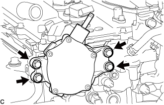
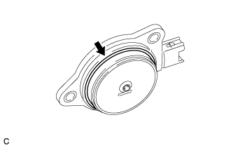
| 1. REMOVE VACUUM PUMP ASSEMBLY |
Remove the 4 bolts and vacuum pump assembly.
 |
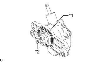
Remove the No. 2 O-ring and No. 3 O-ring from the vacuum pump assembly.
Text in Illustration *1 No. 2 O-ring *2 No. 3 O-ring
 |
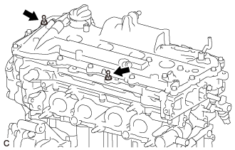
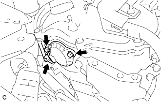
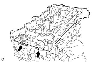
| 2. REMOVE KNOCK CONTROL SENSOR |
Disconnect the knock control sensor connector.
 |
Remove the bolt and knock control sensor from the cylinder block sub-assembly.
- NOTICE:
- If the knock control sensor has been struck or dropped, replace it.
| 3. REMOVE OIL PRESSURE SENDER GAUGE ASSEMBLY |
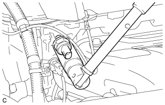
Disconnect the oil pressure sender gauge assembly connector.
Using a 27 mm deep socket wrench, remove the oil pressure sender gauge assembly.
 |
| 4. REMOVE ENGINE COOLANT TEMPERATURE SENSOR |
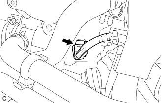
Disconnect the engine coolant temperature sensor connector.
 |
Using SST, remove the engine coolant temperature sensor from the cylinder head sub-assembly.
Text in Illustration *1 Engine Coolant Temperature Sensor *2 Gasket - SST
- 09817-33191
- NOTICE:
- If the engine coolant temperature sensor has been struck or dropped, replace it.
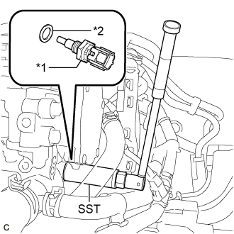 |
Remove the gasket from the engine coolant temperature sensor.
| 5. REMOVE ENGINE COVER JOINT |
Remove the 2 engine cover joints.
 |
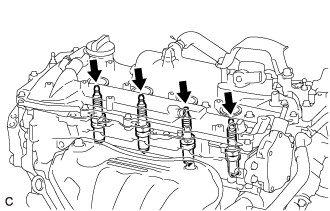
| 6. REMOVE SPARK PLUG |
Remove the 4 spark plugs from the cylinder head sub-assembly.
- NOTICE:
- If a spark plug has been struck or dropped, replace it.
- HINT:
- Arrange the removed parts in the correct order.
 |
| 7. REMOVE OIL FILLER CAP SUB-ASSEMBLY |
Remove the oil filler cap sub-assembly from the cylinder head cover sub-assembly.
Remove the gasket from the oil filler cap sub-assembly.
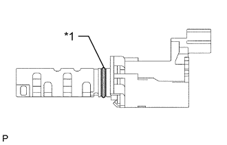
| 8. REMOVE CAMSHAFT TIMING OIL CONTROL VALVE ASSEMBLY |
Disconnect the camshaft timing oil control valve assembly connector.
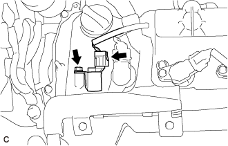 |
Remove the bolt and camshaft timing oil control valve assembly from the cylinder head cover sub-assembly.
- NOTICE:
- Do not allow foreign matter to contact the oil seal face of the camshaft timing oil control valve assembly (connecting surface with the cylinder head cover sub-assembly).
- If the camshaft timing oil control valve assembly has been struck or dropped, replace it.
Remove the O-ring from the camshaft timing oil control valve assembly.
Text in Illustration *1 O-ring
 |
| 9. REMOVE CAMSHAFT POSITION SENSOR (for Intake Side) |
Disconnect the camshaft position sensor connector.
 |
Remove the bolt and camshaft position sensor from the cylinder head cover sub-assembly.
- NOTICE:
- If the camshaft position sensor has been struck or dropped, replace it.
| 10. REMOVE CAMSHAFT POSITION SENSOR (for Exhaust Side) |
Disconnect the camshaft position sensor connector.
 |
Remove the bolt and camshaft position sensor from the cylinder head cover sub-assembly.
- NOTICE:
- If the camshaft position sensor has been struck or dropped, replace it.
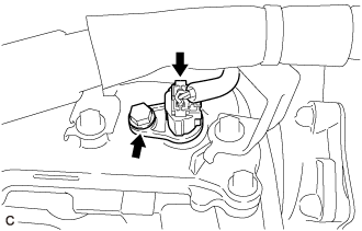
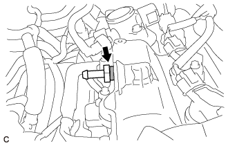
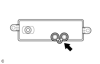
| 11. REMOVE PCV VALVE (VENTILATION VALVE SUB-ASSEMBLY) |
Using a 19 mm deep socket wrench, remove the PCV valve (ventilation valve sub-assembly) from the cylinder head cover sub-assembly.
 |
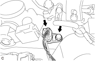
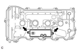
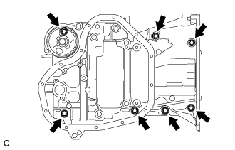
| 12. REMOVE NO. 1 VENTILATION CASE |
Remove the 8 bolts and 2 nuts.
Text in Illustration 
Bolt 
Nut
 |
Remove the No. 1 ventilation case by prying between the No. 1 ventilation case and cylinder block sub-assembly with a screwdriver.
- NOTICE:
- Be careful not to damage the contact surfaces of the cylinder block sub-assembly and No. 1 ventilation case.
- HINT:
- Tape the screwdriver tip before use.
 |
| 13. REMOVE CRANKSHAFT POSITION SENSOR |
Disconnect the crankshaft position sensor connector.
 |
Remove the bolt and crankshaft position sensor from the timing chain cover sub-assembly.
- NOTICE:
- If the crankshaft position sensor has been struck or dropped, replace it.
| 14. REMOVE CRANKSHAFT PULLEY |
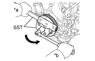
Using SST, hold the crankshaft pulley and loosen the crankshaft pulley set bolt. Further loosen the crankshaft pulley set bolt until 2 or 3 threads are screwed into the crankshaft.
Text in Illustration *a Hold *b Turn - SST
- 09213-54015
09330-00021
- HINT:
- Part number of installation bolt for SST (crankshaft pulley holding tool): 91551-80650 (quantity: 2)
 |
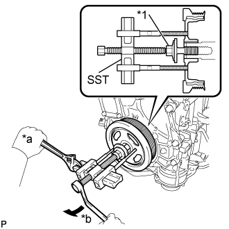
Using SST and the crankshaft pulley set bolt, remove the crankshaft pulley and crankshaft pulley set bolt.
Text in Illustration *1 Crankshaft Pulley Set Bolt *a Hold *b Turn - SST
- 09950-50013
(09951-05010, 09952-05010, 09953-05020, 09954-05011)
- HINT:
- Apply lubricant to the threads and end of SST.
 |
| 15. REMOVE CYLINDER HEAD COVER SUB-ASSEMBLY |
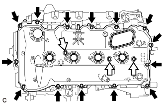
Remove the 17 bolts, 3 seal washers, cylinder head cover sub-assembly and cylinder head cover gasket.
Text in Illustration Bolt Bolt with Seal Washer
 |
Remove the camshaft bearing cap oil hole gasket from the No. 1 camshaft bearing cap.
Text in Illustration *1 Camshaft Bearing Cap Oil Hole Gasket *a Gasket
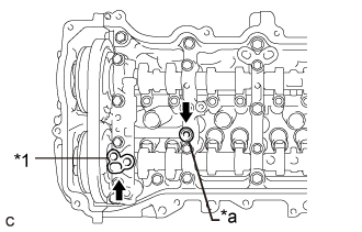 |
Remove the gasket from the No. 2 camshaft bearing cap.
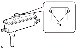
| 16. REMOVE CASE SEPARATOR |
Remove the 2 bolts and case separator from the cylinder head cover case sub-assembly.
 |
Remove the oil separator gasket from the case separator.
 |
Remove the O-ring from the case separator.
Text in Illustration *a O-ring
 |
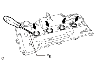
| 17. REMOVE SPARK PLUG TUBE GASKET |
Using a screwdriver, pry out the 4 spark plug tube gaskets from the cylinder head cover sub-assembly.
Text in Illustration *a Protective Tape - NOTICE:
- Be careful not to damage the cylinder head cover sub-assembly.
- HINT:
- Tape the screwdriver tip before use.
 |
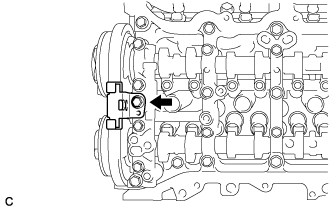
| 18. REMOVE CAMSHAFT TIMING OIL CONTROL SOLENOID ASSEMBLY |
Disconnect the camshaft timing oil control solenoid assembly connector.
 |
Remove the 2 bolts and camshaft timing oil control solenoid assembly from the timing chain cover sub-assembly.
- NOTICE:
- If the camshaft timing oil control solenoid assembly has been struck or dropped, replace it.
Remove the O-ring from the camshaft timing oil control solenoid assembly.
- NOTICE:
- If the O-ring comes off in the timing chain cover sub-assembly, make sure to remove it.
- Do not drop the O-ring into the timing chain cover sub-assembly.
 |
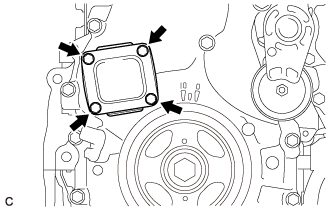
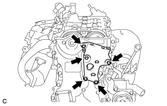
| 19. REMOVE TIMING CHAIN COVER PLATE |
Remove the 4 bolts, timing chain cover plate and gasket.
 |
| 20. REMOVE ENGINE MOUNTING BRACKET RH |
Remove the 5 bolts and engine mounting bracket RH.
 |
| 21. REMOVE TIMING CHAIN COVER SUB-ASSEMBLY |
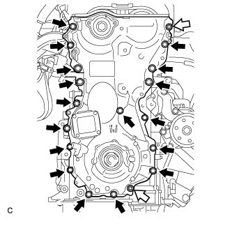
Remove the 17 bolts and 2 nuts.
Text in Illustration Bolt Nut
 |
Remove the timing chain cover sub-assembly by prying between the timing chain cover sub-assembly and cylinder head sub-assembly, camshaft housing sub-assembly, cylinder block and stiffening crankcase assembly with a screwdriver as shown in the illustration.
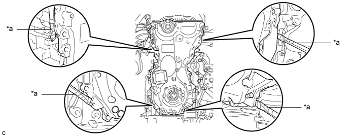
Text in Illustration *a Protective Tape - - - NOTICE:
- Be careful not to damage the contact surfaces of the cylinder head sub-assembly, camshaft housing sub-assembly, cylinder block, stiffening crankcase assembly or timing chain cover sub-assembly.
- HINT:
- Tape the screwdriver tip before use.
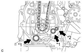
Remove the 2 oil pump gaskets and oil hole cover gasket from the stiffening crankcase assembly.
Text in Illustration *1 Oil Pump Gasket *2 Oil Hole Cover Gasket
 |
| 22. REMOVE TIMING CHAIN COVER OIL SEAL |
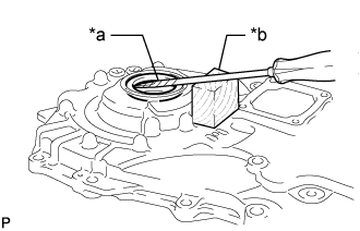
Using a screwdriver and wooden block, pry out the timing chain cover oil seal.
Text in Illustration *a Protective Tape *b Wooden Block - NOTICE:
- Do not damage the surface of the timing chain cover oil seal press fit hole.
- HINT:
- Tape the screwdriver tip before use.
 |
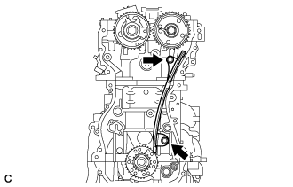
| 23. SET NO. 1 CYLINDER TO TDC/COMPRESSION |
Temporarily install the crankshaft pulley set bolt.
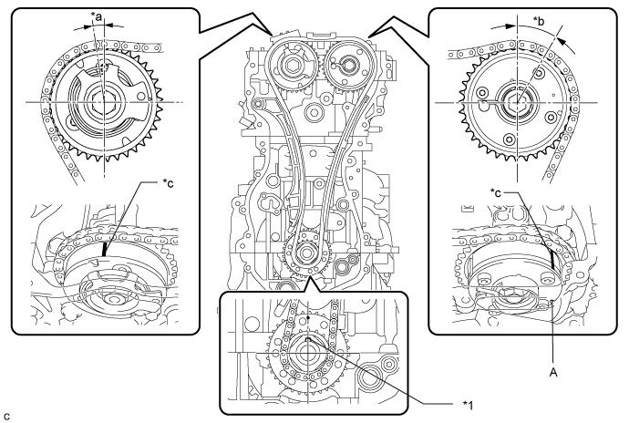
Text in Illustration *1 Crankshaft Pulley Key - - *a Approximately 7° *b Approximately 32° *c Timing Mark - -
Rotate the crankshaft clockwise and align the crankshaft pulley key as shown in the illustration.
Check that the timing marks on the camshaft timing exhaust gear assembly and camshaft timing gear assembly are as shown in the illustration.
- HINT:
- "A" is not a timing mark.
Remove the crankshaft pulley set bolt.
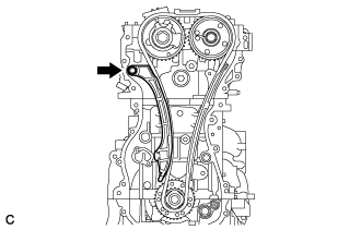
| 24. REMOVE TIMING CHAIN GUIDE |
Remove the bolt and timing chain guide.
 |
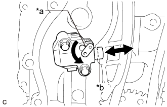
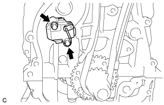
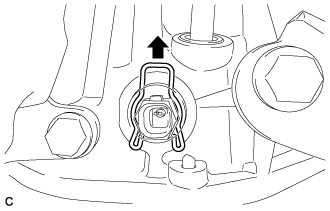
| 25. REMOVE NO. 1 CHAIN TENSIONER ASSEMBLY |
Allow the plunger to extend slightly, and then turn the stopper plate counterclockwise to release the lock. Once the lock is released, push the plunger into the No. 1 chain tensioner assembly.
Text in Illustration *a Stopper Plate *b Plunger
 |
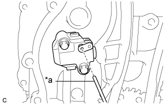
Turn the stopper plate clockwise to set the lock, and insert a pin into the stopper plate hole.
Text in Illustration *a Pin
 |
Remove the 2 bolts, No. 1 chain tensioner assembly and gasket.
 |
| 26. REMOVE CHAIN TENSIONER SLIPPER |
Remove the bolt and chain tensioner slipper.
 |
| 27. REMOVE CHAIN SUB-ASSEMBLY |
Remove the chain sub-assembly.
| 28. REMOVE NO. 1 CHAIN VIBRATION DAMPER |
Remove the 2 bolts and No. 1 chain vibration damper.
 |
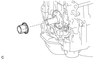
| 29. REMOVE CRANKSHAFT TIMING SPROCKET |
Remove the crankshaft timing sprocket from the crankshaft.
 |
| 30. REMOVE CAMSHAFT TIMING GEAR ASSEMBLY |
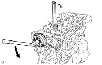
Using a wrench to hold the hexagonal portion of the camshaft, remove the camshaft timing gear bolt and camshaft timing gear assembly.
Text in Illustration *a Hold Turn - NOTICE:
- Be careful not to damage the cylinder head sub-assembly or spark plug tube with the wrench.
- Do not disassemble the camshaft timing gear assembly.
 |
| 31. REMOVE CAMSHAFT TIMING EXHAUST GEAR ASSEMBLY |
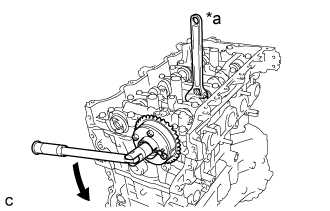
Using a wrench to hold the hexagonal portion of the No. 2 camshaft, remove the bolt and camshaft timing exhaust gear assembly.
Text in Illustration *a Hold Turn - NOTICE:
- Be careful not to damage the cylinder head sub-assembly or spark plug tube with the wrench.
- Do not disassemble the camshaft timing exhaust gear assembly.
 |
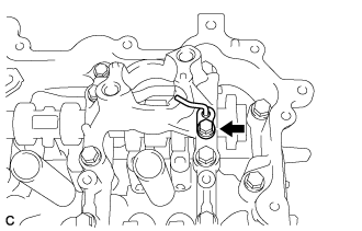
| 32. REMOVE OIL PIPE SUB-ASSEMBLY |
Remove the bolt and oil pipe sub-assembly from the No. 4 camshaft bearing cap.
 |
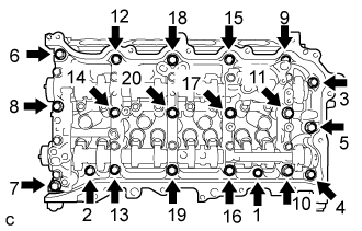
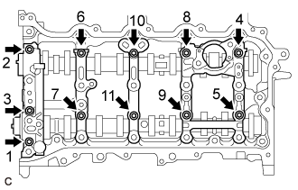
| 33. REMOVE CAMSHAFT HOUSING SUB-ASSEMBLY |
Uniformly loosen and remove the 20 bolts in the order shown in the illustration.
 |
Remove the camshaft housing sub-assembly by prying between the cylinder head sub-assembly and camshaft housing sub-assembly with a screwdriver.
- NOTICE:
- Be careful not to damage the contact surfaces of the cylinder head sub-assembly and camshaft housing sub-assembly.
- HINT:
- Tape the screwdriver tip before use.
 |
| 34. REMOVE CAMSHAFT BEARING CAP |
Remove the 11 bolts in the order shown in the illustration.
 |
Remove the No. 1 camshaft bearing cap, No. 2 camshaft bearing cap, No. 3 camshaft bearing cap and No. 4 camshaft bearing cap.
- HINT:
- Arrange the removed parts in the correct order.
| 35. REMOVE CAMSHAFT |
Remove the camshaft from the camshaft housing sub-assembly.
| 36. REMOVE NO. 2 CAMSHAFT |
Remove the No. 2 camshaft from the camshaft housing sub-assembly.
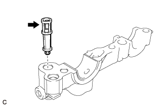
| 37. REMOVE OIL CONTROL VALVE FILTER |
Remove the oil control valve filter from the No. 1 camshaft bearing cap.
 |
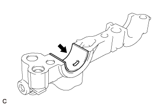
| 38. REMOVE NO. 1 CAMSHAFT BEARING |
Remove the No. 1 camshaft bearing from the No. 1 camshaft bearing cap.
 |
| 39. REMOVE NO. 2 CAMSHAFT BEARING |
Remove the No. 2 camshaft bearing from the camshaft housing sub-assembly.
 |
| 40. REMOVE NO. 1 VALVE ROCKER ARM SUB-ASSEMBLY |
Remove the 16 No. 1 valve rocker arm sub-assemblies.
- HINT:
- Arrange the removed parts in the correct order.
| 41. REMOVE VALVE LASH ADJUSTER ASSEMBLY |
Remove the 16 valve lash adjuster assemblies from the cylinder head sub-assembly.
- HINT:
- Arrange the removed parts in the correct order.
| 42. REMOVE VALVE STEM CAP |
Remove the 16 valve stem caps from the cylinder head sub-assembly.
- HINT:
- Arrange the removed parts in the correct order.
| 43. REMOVE CAMSHAFT HOUSING STUD BOLT |
- NOTICE:
- If a camshaft housing stud bolt is deformed or its threads are damaged, replace it.
| 44. REMOVE CAMSHAFT BEARING CAP SETTING RING PIN |
- NOTICE:
- It is not necessary to remove the camshaft bearing cap setting ring pin unless it is being replaced.
| 45. REMOVE CAMSHAFT HOUSING STRAIGHT PIN |
- NOTICE:
- It is not necessary to remove the camshaft housing straight pin unless it is being replaced.
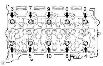
| 46. REMOVE CYLINDER HEAD SUB-ASSEMBLY |
Using a 10 mm bi-hexagon wrench, uniformly loosen the 10 cylinder head set bolts in the order shown in the illustration. Remove the 10 cylinder head set bolts and 10 plate washers.
- HINT:
- Be sure to keep the removed parts separate for each installation position.
- NOTICE:
- Be careful not to drop plate washers into the cylinder head sub-assembly.
- Cylinder head warpage or cracking may result from removing bolts in the incorrect order.
 |
Remove the cylinder head sub-assembly.
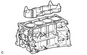
| 47. REMOVE CYLINDER HEAD GASKET |
Remove the cylinder head gasket from the cylinder block sub-assembly.
| 48. REMOVE CYLINDER BLOCK WATER JACKET SPACER |
Remove the cylinder block water jacket spacer from the cylinder block sub-assembly.
- NOTICE:
- Be sure to remove the cylinder block water jacket spacer. If it is not removed, it may fall and become damaged when the cylinder block sub-assembly is inverted.
 |
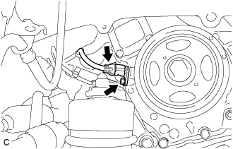
| 49. REMOVE OIL FILTER CAP ASSEMBLY |
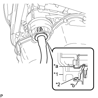
Connect a hose with an inside diameter of 15 mm (0.591 in.) to the pipe.
Text in Illustration *a Pipe *b Hose
 |
Remove the oil filter drain plug from the oil filter cap assembly.
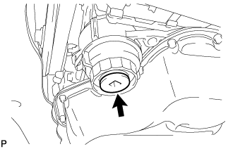 |
Insert the pipe with hose into the oil filter cap assembly.
Text in Illustration *1 Oil Filter Cap Assembly *2 O-ring *a Valve *b Hose - NOTICE:
- Be sure to insert the pipe with the O-ring installed to the oil filter cap assembly.
- HINT:
- Place the hose end into a container before draining the engine oil from the hose.
 |
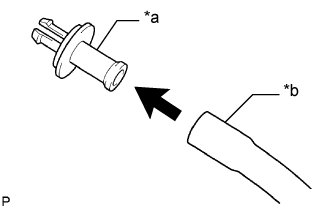
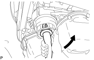
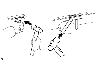
Make sure that the engine oil is completely drained, and remove the pipe with hose and O-ring.
- HINT:
- Pull the pipe with hose as shown in the illustration to remove it.
 |
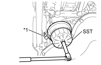
Using SST, remove the oil filter cap assembly.
Text in Illustration *1 Oil Filter Bracket Clip - SST
- 09228-06501
- NOTICE:
- Do not remove the oil filter bracket clip.
 |
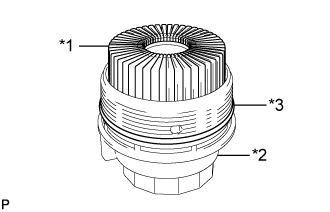
Remove the oil filter element and O-ring from the oil filter cap assembly.
Text in Illustration *1 Oil Filter Element *2 Oil Filter Cap Assembly *3 O-ring - NOTICE:
- Do not use any tools to remove the O-ring in order to prevent the oil filter cap assembly from being damaged. Be sure to remove it by hand.
 |
| 50. REMOVE OIL PAN DRAIN PLUG |
Remove the oil pan drain plug and gasket from the oil pan sub-assembly.
| 51. REMOVE OIL PAN SUB-ASSEMBLY |
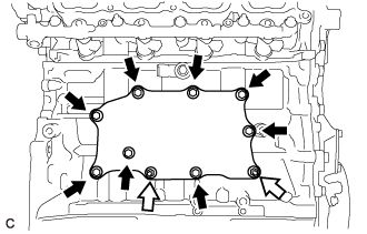
Remove the 11 bolts and 2 nuts.
Text in Illustration *A Type A *B Type B Bolt Nut
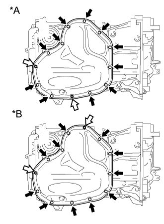 |
Insert the blade of an oil pan seal cutter between the oil pan sub-assembly and stiffening crankcase assembly, cut through the applied sealer and remove the oil pan sub-assembly.
- NOTICE:
- Be careful not to damage the stiffening crankcase assembly contact surface of the oil pan sub-assembly.
- Be careful not to damage the oil pan sub-assembly flange.
 |
| 52. REMOVE OIL STRAINER SUB-ASSEMBLY |
Remove the 3 bolts, oil strainer sub-assembly and gasket.
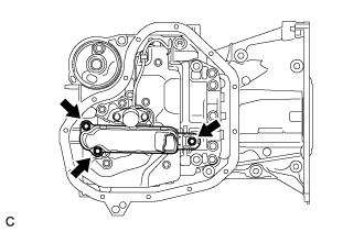 |
| 53. REMOVE ENGINE OIL LEVEL SENSOR |
Disconnect the engine oil level sensor connector.
Remove the clip from the engine oil level sensor.
 |
Remove the 2 bolts.
 |
Disengage the clamp to remove the engine oil level sensor.
| 54. REMOVE OIL LEVEL SENSOR BRACKET |
Remove the 2 bolts and oil level sensor bracket from the stiffening crankcase assembly.
 |
| 55. REMOVE NO. 1 OIL PAN BAFFLE PLATE |
Remove the clamp from the No. 1 oil pan baffle plate.
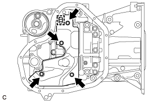 |
Remove the 4 bolts and No. 1 oil pan baffle plate.
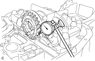
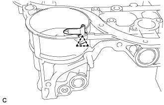
| 56. INSPECT CRANKSHAFT BACKLASH |
Using a dial indicator, measure the backlash of the crankshaft and balance shaft as shown in the illustration.
- Standard Backlash:
- 0.05 to 0.20 mm (0.00197 to 0.00787 in.)
- Maximum Backlash:
- 0.20 mm (0.00787 in.)
 |
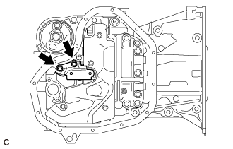
| 57. REMOVE ENGINE BALANCER ASSEMBLY |
Remove the 7 bolts and engine balancer assembly from the stiffening crankcase assembly.
- NOTICE:
- Do not disassemble the engine balancer assembly.
 |
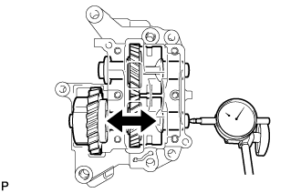
| 58. INSPECT NO. 1 BALANCE SHAFT THRUST CLEARANCE |
Using a dial indicator, measure the thrust clearance while moving the No. 1 balance shaft back and forth.
- Standard Thrust Clearance:
- 0.05 to 0.09 mm (0.00197 to 0.00354 in.)
- Maximum Thrust Clearance:
- 0.09 mm (0.00354 in.)
 |
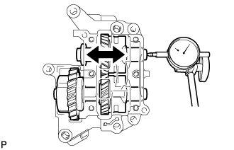
| 59. INSPECT NO. 2 BALANCE SHAFT THRUST CLEARANCE |
Using a dial indicator, measure the thrust clearance while moving the No. 2 balance shaft back and forth.
- Standard Thrust Clearance:
- 0.05 to 0.09 mm (0.00197 to 0.00354 in.)
- Maximum Thrust Clearance:
- 0.09 mm (0.00354 in.)
 |
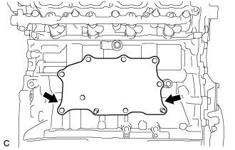
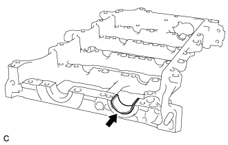
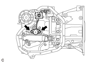
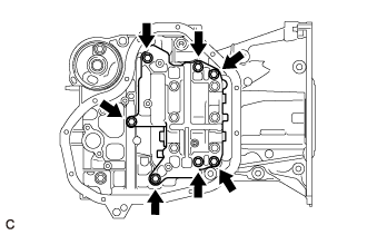
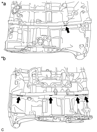
| 60. REMOVE STIFFENING CRANKCASE ASSEMBLY |
Remove the 7 bolts.
 |
Using a screwdriver, remove the stiffening crankcase assembly by prying between the stiffening crankcase assembly and cylinder block sub-assembly at the places shown in the illustration.
Text in Illustration *a LH Side *b RH Side - NOTICE:
- Be careful not to damage the contact surfaces of the cylinder block sub-assembly and stiffening crankcase assembly.
- HINT:
- Tape the screwdriver tip before use.
 |
| 61. REMOVE OIL FILTER BRACKET CLIP |
Remove the oil filter bracket clip from the stiffening crankcase assembly.
 |
| 62. REMOVE STIFFENING CRANKCASE STUD BOLT |
- NOTICE:
- If a stiffening crankcase stud bolt is deformed or its threads are damaged, replace it.
| 63. REMOVE STIFFENING CRANKCASE RING PIN |
- NOTICE:
- It is not necessary to remove the stiffening crankcase ring pin unless it is being replaced.
| 64. REMOVE REAR ENGINE OIL SEAL |
Remove the rear engine oil seal from the cylinder block sub-assembly.