DTC C1ABD Short to +B in Buzzer |
DTC C1ABE Short to GND or Open in Buzzer |

for Preparation Click here
DESCRIPTION
- DTC C1ABD is stored when the blind spot monitor sensor LH detects a +B short in RCTA buzzer (blind spot monitor buzzer) circuit.
- DTC C1ABE is stored when the blind spot monitor sensor LH detects a ground short or open in RCTA buzzer (blind spot monitor buzzer) circuit.
| DTC No. | DTC Detection Condition | Trouble Area |
| C1ABD | When either of the following conditions is met:
|
|
| C1ABE | When either of the following conditions is met:
|
|
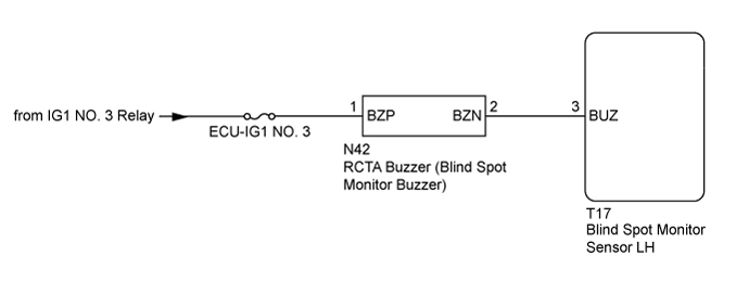
WIRING DIAGRAM
INSPECTION PROCEDURE
- NOTICE:
- When checking for DTCs, make sure that the blind spot monitor main switch (warning canceling switch assembly) is on.
- Inspect the fuses for circuits related to this system before performing the following inspection procedure.
| 1.CHECK DTC |
Clear the DTCs (Click here).
Recheck for DTCs and check if the same DTC is output again.
- OK:
- No DTCs are output.
|
| ||||
| OK | ||
| ||
| 2.CHECK HARNESS AND CONNECTOR (BATTERY, BLIND SPOT MONITOR SENSOR LH - RCTA BUZZER (BLIND SPOT MONITOR BUZZER)) |
Disconnect the T17 blind spot monitor sensor LH connector.
Disconnect the N42 RCTA buzzer (blind spot monitor buzzer) connector.
Measure the resistance according to the value(s) in the table below.
- Standard Resistance:
Tester Connection Condition Specified Condition N42-2 (BZN) - T17-3 (BUZ) Always Below 1 Ω N42-2 (BZN) - Body ground Always 10 kΩ or higher
Measure the voltage according to the value(s) in the table below.
- Standard Voltage:
Tester Connection Condition Specified Condition N42-1 (BZP) - Body ground Ignition switch ON 11 to 14 V N42-1 (BZP) - Body ground Ignition switch off Below 1 V
|
| ||||
| OK | |
| 3.REPLACE RCTA BUZZER (BLIND SPOT MONITOR BUZZER) |
Replace the RCTA buzzer (blind spot monitor buzzer) with a new or known good one (Click here).
| NEXT | |
| 4.CHECK DTC |
Clear the DTCs (Click here).
Recheck for DTCs and check if the same DTC is output again.
- OK:
- No DTCs are output.
|
| ||||
| OK | ||
| ||