DIFFERENTIAL CASE > REASSEMBLY |

for Preparation Click here
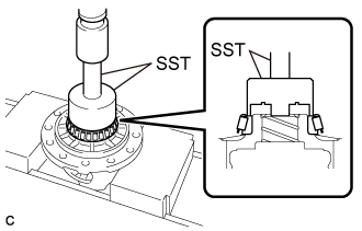
| 1. INSTALL FRONT DIFFERENTIAL CASE REAR TAPERED ROLLER BEARING |
Using SST and a press, install a new front differential case rear tapered roller bearing (inner race) to the front differential case.
- SST
- 09726-36010
09950-70010 (09951-07100)
- NOTICE:
- Do not damage the front differential case rear tapered roller bearing (inner race) cage when installing the front differential case rear tapered roller bearing (inner race).
- Ensure that there is no clearance between the front differential case rear tapered roller bearing (inner race) and front differential case.
 |
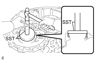
Using SST and a hammer, install a new front differential case rear tapered roller bearing (outer race) to the transaxle case sub-assembly.
- SST
- 09950-60020
(09951-00810)
09950-70010 (09951-07150)
- NOTICE:
- Ensure that there is no clearance between the front differential case rear tapered roller bearing (outer race) and transaxle case sub-assembly.
 |
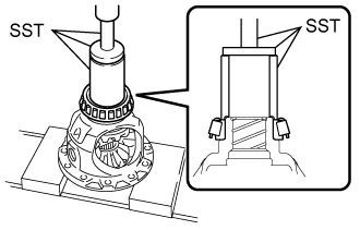
| 2. INSTALL FRONT DIFFERENTIAL CASE FRONT TAPERED ROLLER BEARING |
Using SST and a press, install a new front differential case front tapered roller bearing (inner race) to the front differential case.
- SST
- 09523-36010
09950-60010 (09951-00540)
09950-70010 (09951-07100)
- NOTICE:
- Do not damage the front differential case front tapered roller bearing (inner race) cage when installing the front differential case front tapered roller bearing (inner race).
- Ensure that there is no clearance between the front differential case front tapered roller bearing (inner race) and front differential case.
 |
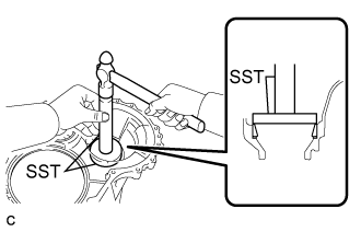
Install the shim to the transaxle housing.
Using SST and a hammer, install a new front differential case front tapered roller bearing (outer race) to the transaxle housing.
- SST
- 09950-60020
(09951-00790)
09950-70010 (09951-07150)
- NOTICE:
- Ensure that there is no clearance between the front differential case front tapered roller bearing (outer race), shim and transaxle housing.
 |
| 3. INSTALL FRONT DIFFERENTIAL SIDE GEAR |
Coat the 2 front differential side gears, 2 front No. 1 differential side gear thrust washers and 2 conical springs with ATF.
Text in Illustration *1 Front Differential Side Gear *2 Conical Spring *3 Front No. 1 Differential Side Gear Thrust Washer 
ATF
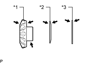 |
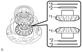
Install the 2 front differential side gears, 2 front No. 1 differential side gear thrust washers and 2 conical springs to the front differential case.
Text in Illustration *1 Front Differential Side Gear *2 Conical Spring *3 Front No. 1 Differential Side Gear Thrust Washer - NOTICE:
- Do not drop the front differential side gear, front No. 1 differential side gear thrust washer or conical spring.
- Make sure that the conical spring is installed with the correct orientation.
 |
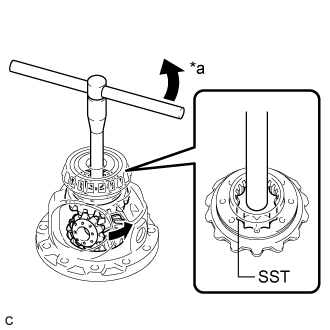
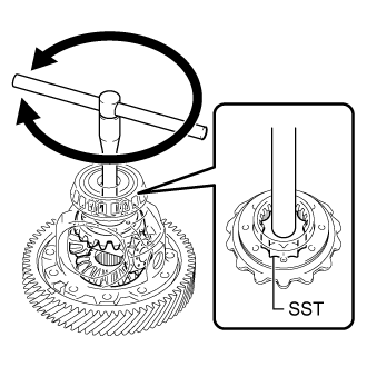
Install SST as shown in the illustration and tighten it.
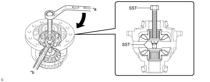
Text in Illustration *a Turn *b Hold - SST
- 09528-52010
(09528-05010, 09953-05010)
- NOTICE:
- Do not overtighten SST as doing so will damage the front differential side gears, conical springs, front No. 1 differential side gear thrust washers and front differential case.
- HINT:
- Tighten SST to create the necessary clearance to install the front differential pinions.
- When installing the front differential pinions, do not overtighten SST, as it is necessary to rotate the front differential side gears.
Coat the 2 front differential pinions and 2 front differential pinion thrust washers with ATF.
Text in Illustration ATF
 |
Using SST as shown in the illustration, rotate the front differential side gear to install the 2 front differential pinions and 2 front differential pinion thrust washers to the front differential case.
Text in Illustration *a Turn - SST
- 09528-52010
(09528-05030)
- CAUTION:
- Be careful not to catch your fingers between the front differential pinion and front differential case.
- NOTICE:
- Do not drop the front differential pinion or front differential pinion thrust washer.
 |
| 4. INSPECT FRONT DIFFERENTIAL PINION BACKLASH |
Install SST as shown in the illustration and tighten it.
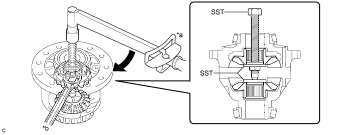
Text in Illustration *a Turn *b Hold - SST
- 09528-52010
(09528-05010, 09953-05010)
- Torque:
- 10 N*m{ 102 kgf*cm , 7 ft.*lbf }
Secure the front differential case in a vise between aluminum plates.
- NOTICE:
- Do not overtighten the vise.
Install the front No. 1 differential pinion shaft to the front differential pinion as shown in the illustration.
Text in Illustration *1 Front No. 1 Differential Pinion Shaft
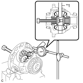 |
Using a dial indicator, measure the front differential pinion backlash.
- Standard Backlash:
- 0.20 mm (0.00787 in.) or less
- HINT:
- Select front No. 1 differential side gear thrust washers of the same thickness for both the right and left side.
Front No. 1 Differential Side Gear Thrust Washer Thickness: Part No. Thickness (mm (in.)) 41361-73050 0.90 (0.0354) 41361-73010 1.00 (0.0394) 41361-73020 1.10 (0.0433) 41361-73030 1.20 (0.0472)
| 5. INSTALL FRONT NO. 1 DIFFERENTIAL PINION SHAFT |
Coat the front No. 1 differential pinion shaft with ATF.
Text in Illustration ATF
 |
Install the front No. 1 differential pinion shaft to the front differential case so that the hole for the front differential pinion shaft straight pin is aligned with the hole in the front differential case.
| 6. INSPECT FRONT DIFFERENTIAL CASE |
Using SST, rotate the front differential side gear as shown in the illustration.
- SST
- 09528-52010
(09528-05030)
- Standard:
- The front differential side gear does not lock when rotated in either direction.
- If the front differential side gear locks, perform all inspections.
- If the front differential side gear still locks even after replacing the malfunctioning parts, replace the front differential case.
- Replace any parts that do not meet the specification.
 |
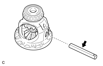
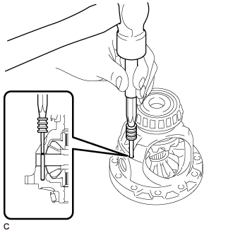
| 7. INSTALL FRONT DIFFERENTIAL PINION SHAFT STRAIGHT PIN |
Using a 5 mm pin punch and a hammer, install the front differential pinion shaft straight pin to the front differential case.
 |
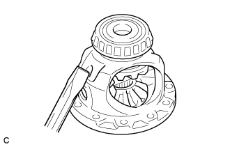
Using a chisel and hammer, stake the front differential case.
 |
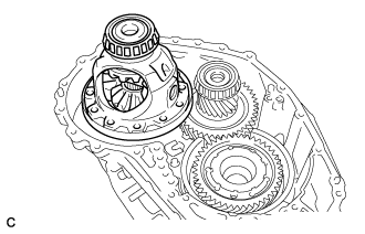
| 8. ADJUST DIFFERENTIAL SIDE BEARING PRELOAD |
Remove any remaining seal packing from the contact surfaces of the transaxle housing and transaxle case sub-assembly.
Install the front differential case to the transaxle case sub-assembly.
 |
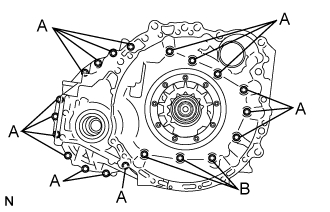
Install the transaxle housing to the transaxle case sub-assembly with the 20 bolts.
- Torque:
- Bolt (A):
- 31 N*m{ 316 kgf*cm , 23 ft.*lbf }
- Bolt (B):
- 23 N*m{ 234 kgf*cm , 17 ft.*lbf }
 |
Using SST, turn the front differential case right and left 2 or 3 times to settle the bearings.
- SST
- 09564-33010
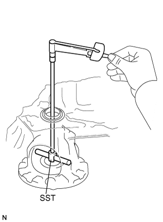 |
Using SST and a torque wrench, measure the turning torque of the differential side bearing while rotating SST at 10 rpm.
- SST
- 09564-33010
- Turning Torque:
- 1.3 to 1.7 N*m (13 to 17 kgf*cm, 12 to 15 in.*lbf)
Shim Thickness Part No. Thickness
(mm (in.))90564-69001 2.000 (0.0787) 90564-69002 2.025 (0.0797) 90564-69003 2.050 (0.0807) 90564-69004 2.075 (0.0817) 90564-69005 2.100 (0.0827) 90564-69006 2.125 (0.0837) 90564-69007 2.150 (0.0846) 90564-69008 2.175 (0.0856) 90564-69009 2.200 (0.0866) 90564-69010 2.225 (0.0876) 90564-69011 2.250 (0.0886) 90564-69012 2.275 (0.0896) 90564-69013 2.300 (0.0906) 90564-69014 2.325 (0.0915) 90564-69015 2.350 (0.0925) 90564-69016 2.375 (0.0935) 90564-69017 2.400 (0.0945) 90564-69020 2.425 (0.0955) 90564-69021 2.450 (0.0965) 90564-69022 2.475 (0.0974) 90564-69023 2.500 (0.0984) 90564-69024 2.525 (0.0994) 90564-69025 2.550 (0.100) 90564-69026 2.575 (0.101) 90564-69027 2.600 (0.102) 90564-69028 2.625 (0.103) 90564-69029 2.650 (0.104) 90564-69030 2.675 (0.105) 90564-69031 2.700 (0.106) 90564-69032 2.725 (0.107) 90564-69033 2.750 (0.108) 90564-69034 2.775 (0.109) 90564-69035 2.800 (0.110) 90564-69036 2.825 (0.111) 90564-69037 2.850 (0.112) 90564-69038 2.875 (0.113)
Remove the 20 bolts and transaxle housing from the transaxle case sub-assembly.
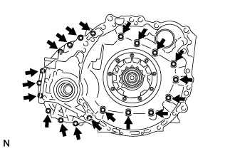 |
Remove the front differential case from the transaxle case sub-assembly.
|
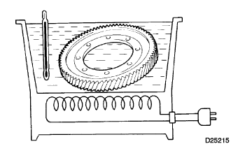
| 9. INSTALL FRONT DIFFERENTIAL RING GEAR |
Using ATF and a heater, heat the front differential ring gear to 90 to 110°C (194 to 230°F).
- NOTICE:
- Do not heat the front differential ring gear to more than 110°C (230°F).
 |
Clean the contact surface of the front differential case.
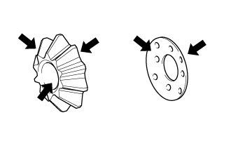
Align the matchmarks, and install the front differential ring gear to the front differential case quickly.
Text in Illustration *a Matchmark
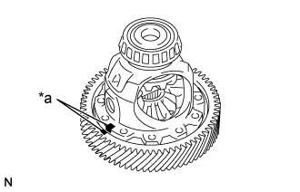 |
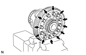
Install the 12 bolts.
- Torque:
- 120 N*m{ 1224 kgf*cm , 89 ft.*lbf }
- NOTICE:
- Tighten the bolts after the front differential ring gear has cooled down sufficiently.
- Tighten the bolts evenly in a diagonal pattern using several steps.
 |
| 10. INSTALL TRANSAXLE CASE OIL SEAL |
Coat the lip of a new transaxle case oil seal with MP grease.
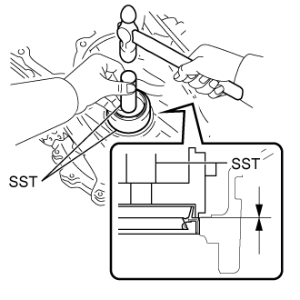
Using SST and a hammer, install the transaxle case oil seal to the transaxle case sub-assembly.
- SST
- 09316-10010
09950-70010 (09951-07100)
- Standard Depth:
- -0.5 to 0.5 mm (-0.0197 to 0.0197 in.)
- NOTICE:
- Make sure that the transaxle case oil seal is installed in the correct direction.
- Do not damage the lip of the transaxle case oil seal.
 |
| 11. INSTALL FRONT TRANSAXLE CASE OIL SEAL |
Coat the lip of a new front transaxle case oil seal with MP grease.
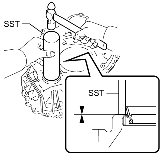
Using SST and a hammer, install the front transaxle case oil seal to the transaxle housing.
- SST
- 09308-14010
- Standard Depth:
- -0.5 to 0.5 mm (-0.0197 to 0.0197 in.)
- NOTICE:
- Make sure that the front transaxle case oil seal is installed in the correct direction.
- Do not damage the lip of the front transaxle case oil seal.
 |