REAR VIEW MONITOR SYSTEM > Image from Camera for Rear View Monitor is Abnormal |

for Preparation Click here
DESCRIPTION
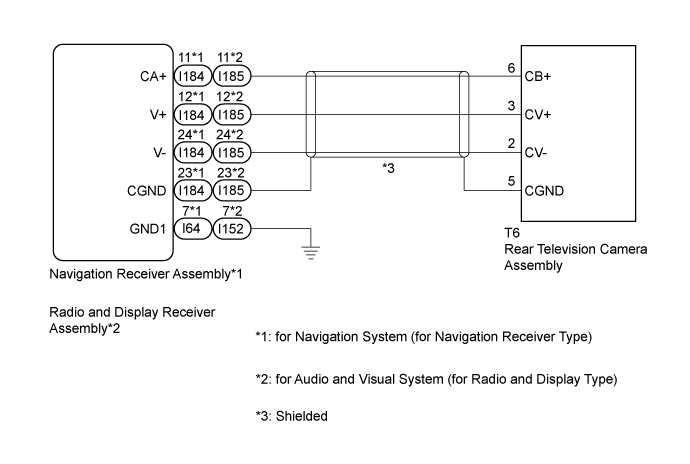
- The video signal of the rear television camera assembly is transmitted to the navigation receiver assembly*1 or radio and display receiver assembly*2.
*1: for Navigation System (for Navigation Receiver Type)
*2: for Audio and Visual System (for Radio and Display Type)
WIRING DIAGRAM
INSPECTION PROCEDURE
| 1.CONFIRM MODEL |
Choose the model to be inspected.
- Result:
Result Proceed to for Navigation System (for Navigation Receiver Type) A for Audio and Visual System (for Radio and Display Type) B
|
| ||||
| A | |
| 2.CHECK HARNESS AND CONNECTOR (NAVIGATION RECEIVER ASSEMBLY - REAR TELEVISION CAMERA ASSEMBLY) |
Disconnect the I184 navigation receiver assembly connector.
Disconnect the T6 rear television camera assembly connector.
Measure the resistance according to the value(s) in the table below.
- Standard Resistance:
Tester Connection Condition Specified Condition I184-11 (CA+) - T6-6 (CB+) Always Below 1 Ω I184-12 (V+) - T6-3 (CV+) Always Below 1 Ω I184-24 (V-) - T6-2 (CV-) Always Below 1 Ω I184-23 (CGND) - T6-5 (CGND) Always Below 1 Ω I184-11 (CA+) - Body ground Always 10 kΩ or higher I184-12 (V+) - Body ground Always 10 kΩ or higher I184-24 (V-) - Body ground Always 10 kΩ or higher I184-23 (CGND) - Body ground Always 10 kΩ or higher
|
| ||||
| OK | |
| 3.INSPECT NAVIGATION RECEIVER ASSEMBLY |
Reconnect the I184 navigation receiver assembly connector.
Measure the resistance according to the value(s) in the table below.
- Standard Resistance:
Tester Connection Condition Specified Condition I184-23 (CGND) - Body ground Always Below 1 Ω
 |
Measure the voltage according to the value(s) in the table below.
- Standard Voltage:
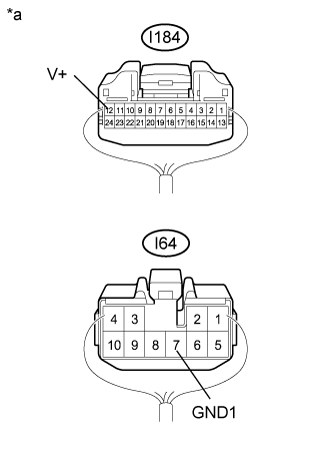
Tester Connection Condition Specified Condition I184-11 (CA+) - I184-23 (CGND) Ignition switch ACC 5.5 to 7.05 V
Text in Illustration *a Component with harness connected
(Navigation Receiver Assembly)
- Result:
Result Proceed to OK A NG (for TMC, TMMR Made) B NG (for TMMK Made) C
|
| ||||
|
| ||||
| A | |
| 4.INSPECT REAR TELEVISION CAMERA ASSEMBLY |
Reconnect the T6 rear television camera assembly connector.
Using an oscilloscope, check the waveform of the rear television camera assembly.
Text in Illustration *a Component with harness connected
(Navigation Receiver Assembly)- HINT:
- A waterproof connector is used for the rear television camera assembly. Therefore, inspect the waveform at the navigation receiver assembly with the connector connected.
- OK:
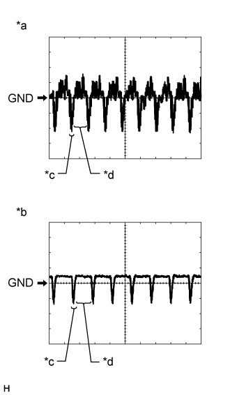
- Waveform is similar to that shown in the illustration.
Item Content Measurement terminal I184-12 (V+) - I64-7 (GND1) Measurement setting 200 mV/DIV., 50 μs./DIV. Condition Ignition switch ON, shift lever in R - HINT:
- The video waveform changes according to the image sent by the rear television camera assembly.
- The video waveform is constantly output when the ignition switch is turned to ACC.
Text in Illustration *a Waveform 1 (camera lens is not covered, displaying an image) *b Waveform 2 (camera lens is covered, blacking out the screen) *c Synchronization Signal *d Video Waveform
  |
- Result:
Result Proceed to OK (for TMC, TMMR Made) A OK (for TMMK Made) B NG (for TMC, TMMR Made) C NG (for TMMK Made) D
|
| ||||
|
| ||||
|
| ||||
| A | ||
| ||
| 5.CHECK HARNESS AND CONNECTOR (RADIO AND DISPLAY RECEIVER ASSEMBLY - REAR TELEVISION CAMERA ASSEMBLY) |
Disconnect the I185 radio and display receiver assembly connector.
Disconnect the T6 rear television camera assembly connector.
Measure the resistance according to the value(s) in the table below.
- Standard Resistance:
Tester Connection Condition Specified Condition I185-11 (CA+) - T6-6 (CB+) Always Below 1 Ω I185-12 (V+) - T6-3 (CV+) Always Below 1 Ω I185-24 (V-) - T6-2 (CV-) Always Below 1 Ω I185-23 (CGND) - T6-5 (CGND) Always Below 1 Ω I185-11 (CA+) - Body ground Always 10 kΩ or higher I185-12 (V+) - Body ground Always 10 kΩ or higher I185-24 (V-) - Body ground Always 10 kΩ or higher I185-23 (CGND) - Body ground Always 10 kΩ or higher
|
| ||||
| OK | |
| 6.INSPECT RADIO AND DISPLAY RECEIVER ASSEMBLY |
Reconnect the I185 radio and display receiver assembly connector.
Measure the resistance according to the value(s) in the table below.
- Standard Resistance:
Tester Connection Condition Specified Condition I185-23 (CGND) - Body ground Always Below 1 Ω
 |
Measure the voltage according to the value(s) in the table below.
- Standard Voltage:
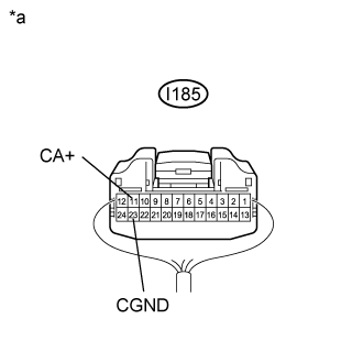
Tester Connection Condition Specified Condition I185-11 (CA+) - I185-23 (CGND) Ignition switch ACC 5.5 to 7.05 V
Text in Illustration *a Component with harness connected
(Radio and Display Receiver Assembly)
- Result:
Result Proceed to OK A NG (for TMC, TMMR Made) B NG (for TMMK Made) C
|
| ||||
|
| ||||
| A | |
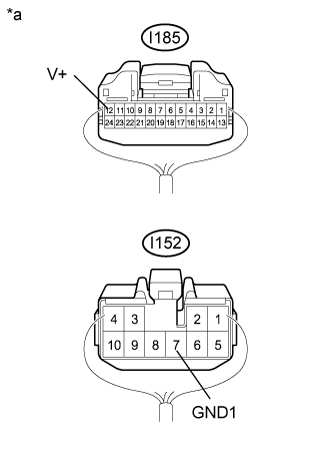
| 7.INSPECT REAR TELEVISION CAMERA ASSEMBLY |
Reconnect the T6 rear television camera assembly connector.
Using an oscilloscope, check the waveform of the rear television camera assembly.
Text in Illustration *a Component with harness connected
(Radio and Display Receiver Assembly)- HINT:
- A waterproof connector is used for the rear television camera assembly. Therefore, inspect the waveform at the radio and display receiver assembly with the connector connected.
- OK:
- Waveform is similar to that shown in the illustration.
Item Content Measurement terminal I185-12 (V+) - I152-7 (GND1) Measurement setting 200 mV/DIV., 50 μs./DIV. Condition Ignition switch ON, shift lever in R - HINT:
- The video waveform changes according to the image sent by the rear television camera assembly.
- The video waveform is constantly output when the ignition switch is turned to ACC.
Text in Illustration *a Waveform 1 (camera lens is not covered, displaying an image) *b Waveform 2 (camera lens is covered, blacking out the screen) *c Synchronization Signal *d Video Waveform
 |
- Result:
Result Proceed to OK (for TMC, TMMR Made) A OK (for TMMK Made) B NG (for TMC, TMMR Made) C NG (for TMMK Made) D
|
| ||||
|
| ||||
|
| ||||
| A | ||
| ||