SHIFT LEVER > INSTALLATION |

for Preparation Click here
| 1. INSTALL SHIFT LEVER SUPPORT |
Install the shift lever support to the vehicle body with the 4 bolts in the order shown in the illustration.
- Torque:
- 12 N*m{ 122 kgf*cm , 9 ft.*lbf }
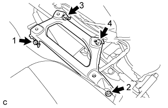 |
| 2. INSTALL LOWER SHIFT LEVER ASSEMBLY |
- NOTICE:
- Check that the park/neutral position switch assembly and the shift lever are in neutral.
Install the lower shift lever assembly to the shift lever support with the 4 bolts.
- Torque:
- 12 N*m{ 122 kgf*cm , 9 ft.*lbf }
Connect the 2 connectors.
Engage the 3 clamps to connect the wire harness to the lower shift lever assembly.
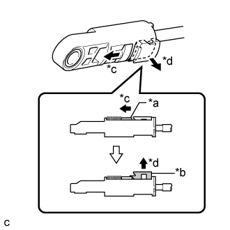
Slide the slider of the transmission control cable assembly as shown in the illustration and pull the lock piece outward.
Text in Illustration *a Slider *b Lock Piece *c Slide *d Pull
 |
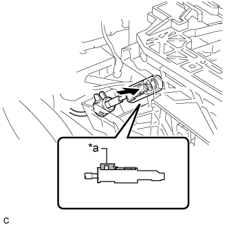
Engage the 2 claws to connect the transmission control cable assembly to the lower shift lever assembly.
Connect the end of the transmission control cable assembly to the lower shift lever assembly.
Text in Illustration *a Lock Piece - NOTICE:
- Check that the lock piece is pulled out.
- Push the end of the transmission control cable assembly all the way to the base of the lower shift lever assembly pin.
 |
Push the lock piece into the adjuster case.
- NOTICE:
- Check that the park/neutral position switch assembly and the shift lever are in neutral.
- Securely push in the lock piece until the slider lock is engaged.
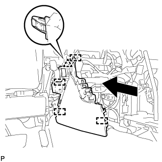
| 3. INSTALL NO. 1 CONSOLE BOX DUCT |
Install the No. 1 console box duct with the clip.
| 4. INSTALL NO. 1 CONSOLE BOX MOUNTING BRACKET |
Install the No. 1 console box mounting bracket to the lower shift lever assembly with the screw.
| 5. INSTALL FLOOR CARPET BRACKET LH |
Engage the 2 guides.
Install the floor carpet bracket LH with the 2 clips.
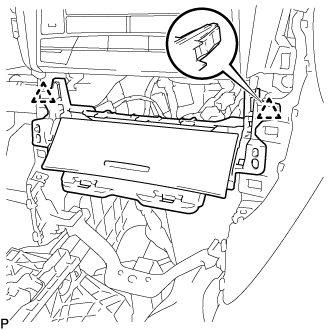
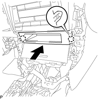
| 6. INSTALL CONSOLE BOX INSERT |
Engage the clip and 4 guides as shown in the illustration.
 |
Install the console box insert with the 2 screws <D>.
for RHD:
Engage the 2 claws to connect the room temperature sensor.
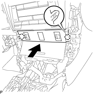
| 7. INSTALL FRONT NO. 2 CONSOLE BOX INSERT |
Engage the clip and 4 guides as shown in the illustration.
 |
Install the front No. 2 console box insert with the 2 screws <D>.
for LHD:
Engage the 2 claws to connect the room temperature sensor.
| 8. INSTALL FRONT ASH RECEPTACLE ASSEMBLY |
Connect each connector.
Engage the 2 clips.
 |
Install the front ash receptacle assembly with the 2 screws <D>.
| 9. INSTALL FRONT CONSOLE UPPER PANEL GARNISH |
for Blank Type:
Engage the 2 claws to install the front console upper panel garnish as shown in the illustration.
for 3 Switch Hole Type:
Connect each connector.
Engage the 2 claws to install the front console upper panel garnish as shown in the illustration.
| 10. INSTALL LOWER INSTRUMENT PANEL SUB-ASSEMBLY |
Engage the 2 clips and 4 guides.
 |
Install the 3 screws <D>.
Close the lower instrument panel door.
Install the lower instrument panel sub-assembly with the bolt <B> and screws <D>.
| 11. INSTALL NO. 2 INSTRUMENT PANEL UNDER COVER SUB-ASSEMBLY |
Connect the connector.
Engage the 2 guides and 4 claws to install the No. 2 instrument panel under cover sub-assembly.
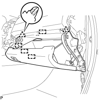
| 12. INSTALL INSTRUMENT SIDE PANEL RH |
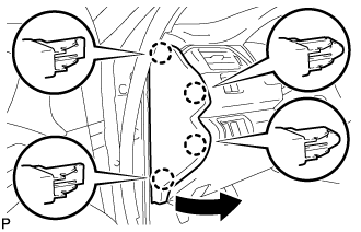
Engage the 3 guides as shown in the illustration.
 |
Engage the 4 claws to install the instrument side panel RH as shown in the illustration.
 |
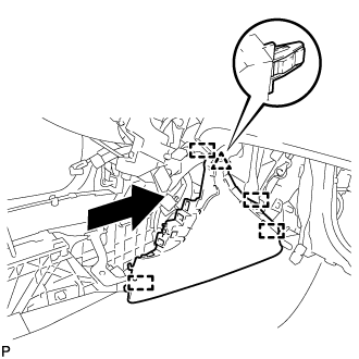
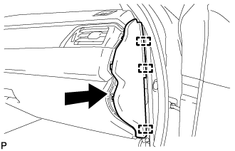
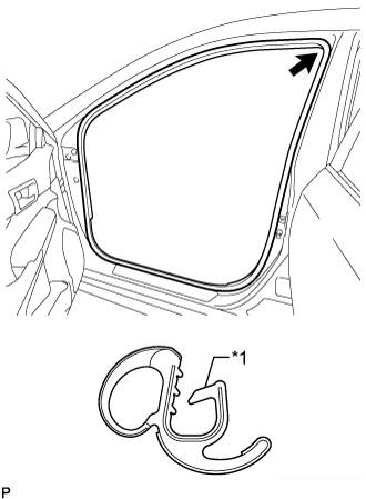
| 13. INSTALL FRONT DOOR OPENING TRIM WEATHERSTRIP RH |
Align the alignment mark (White) on the weatherstrip with the protruding portion on the body indicated by the arrow in the illustration, and install the front door opening trim weatherstrip RH.
Text in Illustration *1 Alignment Mark (White) - NOTICE:
- After installation, check that the corners fit correctly.
 |
| 14. INSTALL COWL SIDE TRIM SUB-ASSEMBLY RH |
- HINT:
- Use the same procedure as for the LH side.
| 15. INSTALL FRONT DOOR SCUFF PLATE RH |
- HINT:
- Use the same procedure as for the LH side (Click here).
| 16. INSTALL INSTRUMENT PANEL SUB-ASSEMBLY |
w/o Driver Side Knee Airbag:
Engage the 5 clips and 3 guides.
w/ Driver Side Knee Airbag:
Engage the 4 claws, 7 clips and 3 guides.
Install the instrument panel sub-assembly with the 2 bolts <B>.
| 17. CONNECT HOOD LOCK CONTROL LEVER SUB-ASSEMBLY |
Engage the claw and 2 guides to connect the hood lock control lever sub-assembly.
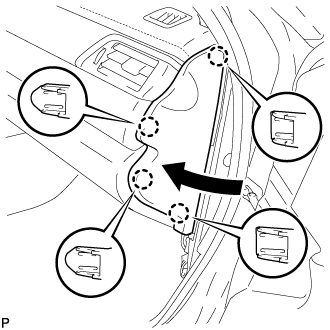
| 18. INSTALL INSTRUMENT SIDE PANEL LH |
Engage the 3 guides.
Engage the 4 claws to install the instrument side panel LH as shown in the illustration.
 |
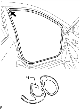
| 19. INSTALL FRONT DOOR OPENING TRIM WEATHERSTRIP LH |
Align the alignment mark (Yellow) on the weatherstrip with the protruding portion on the body indicated by the arrow in the illustration, and install the front door opening trim weatherstrip LH.
Text in Illustration *1 Alignment Mark (Yellow) - NOTICE:
- After installation, check that the corners fit correctly.
 |
| 20. INSTALL COWL SIDE TRIM SUB-ASSEMBLY LH |
Engage the 2 clips.
Install the cowl side trim sub-assembly LH with the clip.
| 21. INSTALL FRONT DOOR SCUFF PLATE LH |
Engage the 10 claws to install the front door scuff plate LH.
| 22. INSTALL CONSOLE BOX ASSEMBLY |
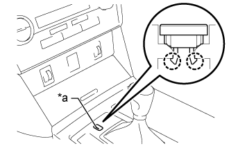
| 23. INSTALL SHIFT LOCK RELEASE BUTTON COVER |
Engage the 2 claws to install the shift lock release button cover to the shift position indicator.
Text in Illustration *a Groove - NOTICE:
- Install the shift lock release button cover with its groove facing the left of the vehicle.
 |
| 24. INSPECT SHIFT LEVER POSITION |
When the shift lever is moved from P to R with the engine switch ON and brake pedal depressed, make sure that the shift lever moves smoothly and correctly to P.
Start the engine and check that the vehicle moves forward when the shift lever is moved from N to D and moves rearward when the shift lever is moved to R.