DTC B15C0 Short in GPS Antenna |
DTC B15C1 Open in GPS Antenna |

for Preparation Click here
DESCRIPTION
These DTCs are stored when a malfunction occurs in the navigation antenna assembly.| DTC No. | DTC Detection Condition | Trouble Area |
| B15C0 | Navigation antenna malfunction |
|
| B15C1 | Navigation antenna power source malfunction |
- *: w/ Heated Windshield Defroster System
INSPECTION PROCEDURE
- NOTICE:
- Check that the navigation antenna assembly cable is properly installed and does not have any sharp bends, pinching or loose connections before performing the following inspection procedure (Click here).
| 1.CHECK DTC |
Clear the DTCs (Click here).
Recheck for DTCs and check that no DTCs are output.
- OK:
- No DTCs are output.
|
| ||||
| OK | ||
| ||
| 2.CHECK MODEL |
Choose the model to be inspected.
- Result:
Result Proceed to w/ Heated Windshield Defroster System A w/o Heated Windshield Defroster System B
|
| ||||
| A | |
| 3.CHECK ANTENNA CORD SUB-ASSEMBLY |
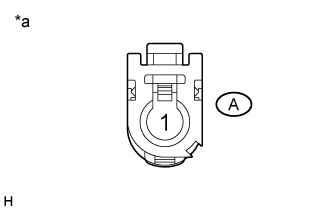
Disconnect the antenna cord sub-assembly connector from the radio and display receiver assembly.
Text in Illustration *a Antenna cord sub-assembly connector
(to Radio and Display Receiver Assembly)
 |
Disconnect the antenna cord sub-assembly connector from the No. 2 antenna cord sub-assembly.
Text in Illustration *a Antenna cord sub-assembly connector
(to No. 2 Antenna Cord Sub-assembly)
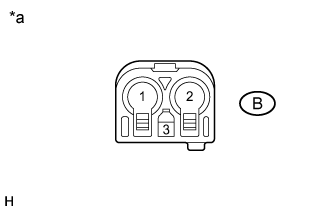 |
Measure the resistance according to the value(s) in the table below.
- Standard Resistance:
Tester Connection Condition Specified Condition A-1 - B-1 Always Below 1 Ω A-1 - Body ground Always 10 kΩ or higher
|
| ||||
| OK | |
| 4.CHECK NO. 2 ANTENNA CORD SUB-ASSEMBLY |
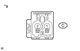
Disconnect the No. 2 antenna cord sub-assembly connector from the antenna cord sub-assembly.
Text in Illustration *a No. 2 antenna cord sub-assembly connector
(to Antenna Cord Sub-assembly)
 |
Disconnect the No. 2 antenna cord sub-assembly connector from wire harness.
Text in Illustration *a No. 2 antenna cord sub-assembly connector
(to Wire Harness)
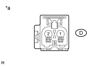 |
Measure the resistance according to the value(s) in the table below.
- Standard Resistance:
Tester Connection Condition Specified Condition C-1 - D-2 Always Below 1 Ω C-1 - Body ground Always 10 kΩ or higher
|
| ||||
| OK | |
| 5.CHECK HARNESS AND CONNECTOR (NAVIGATION ANTENNA ASSEMBLY - NO. 2 ANTENNA CORD SUB-ASSEMBLY) |
Disconnect the wire harness connector from the No. 2 antenna cord sub-assembly connector.
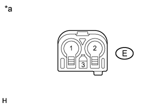
Text in Illustration *a Front view of wire harness connector
(to No. 2 Antenna Cord Sub-assembly)
 |
Disconnect the wire harness connector from the navigation antenna assembly.
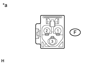
Text in Illustration *a Front view of wire harness connector
(to Navigation Antenna Assembly)
 |
Measure the resistance according to the value(s) in the table below.
- Standard Resistance:
Tester Connection Condition Specified Condition E-2 - F-2 Always Below 1 Ω E-1 - Body ground Always 10 kΩ or higher
|
| ||||
| OK | |
| 6.INSPECT NAVIGATION ANTENNA ASSEMBLY |
Remove the navigation antenna assembly (Click here).
Measure the resistance according to the value(s) in the table below.
- Standard Resistance:
Tester Connection Condition Specified Condition 2 - 2a Always 50 to 500 Ω
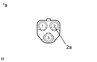 |
| *a | Component without harness connected (Navigation Antenna Assembly) |
|
| ||||
| OK | ||
| ||
| 7.INSPECT NAVIGATION ANTENNA ASSEMBLY |
Remove the navigation antenna assembly (Click here).
Measure the resistance according to the value(s) in the table below.
- Standard Resistance:
Tester Connection Condition Specified Condition 1 - 1a Always 50 to 500 Ω
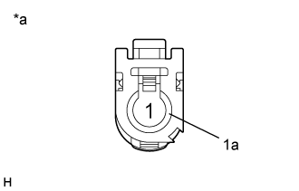 |
| *a | Component without harness connected (Navigation Antenna Assembly) |
|
| ||||
| OK | ||
| ||