AUDIO AND VISUAL SYSTEM (for Radio Receiver Type) > Radio Broadcast cannot be Received or Poor Reception |

for Preparation Click here
INSPECTION PROCEDURE
| 1.CHECK RADIO RECEIVER ASSEMBLY |
Check the radio automatic station search function.
Check the radio automatic station search function by activating it.
- Result:
Result Proceed to Automatic station search function does not stop A Automatic station search function stops on a station B
|
| ||||
| A | |
| 2.CHECK OPTIONAL COMPONENTS |
Check if any optional components that may decrease reception capacity, such as sunshade film, are installed.
- Result:
Result Proceed to Optional components are installed A Optional components are not installed B
- NOTICE:
- Do not remove optional components without the permission of the customer.
|
| ||||
| A | ||
| ||
| 3.CHECK RADIO RECEIVER ASSEMBLY |
Preparation for check
Remove the antenna connector from the radio receiver assembly.
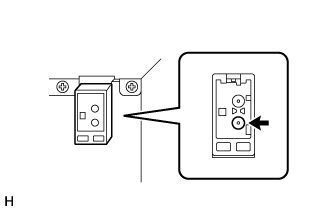 |
Check for noise
Turn the engine switch on (ACC) with the radio receiver assembly connector connected.
Turn the radio on and tune into AM mode.
Place a screwdriver, thin wire or other metal object on the radio receiver assembly antenna jack and check that noise can be heard from the speakers.
- OK:
- Noise occurs.
|
| ||||
| OK | |
| 4.CHECK WINDOW GLASS ANTENNA WIRE |
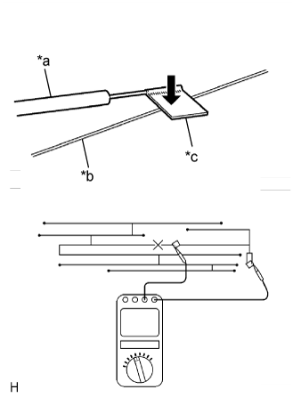
Check for continuity of the window glass antenna wire.
- HINT:
- Check for continuity at the center of each antenna wire as shown in the illustration.
- NOTICE:
- When cleaning the glass, wipe it in the direction of the wire with a soft dry cloth. Take care not to damage the wire. Do not use detergents or glass cleaners with abrasive ingredients. When measuring resistance, wrap a piece of tin foil around the tip of each probe and press the foil against the wire with your finger, as shown in the illustration.
- OK:
- There is continuity in the window glass antenna wire.
Text in Illustration *a Tester Probe *b Antenna Wire *c Tin Foil
 |
|
| ||||
| OK | |
| 5.INSPECT RADIO RECEIVER ASSEMBLY |
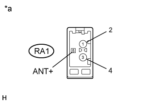
Disconnect the RA1 radio receiver assembly connector.
Measure the voltage according to the value(s) in the table below.
- Standard Voltage:
Tester Connection Condition Specified Condition RA1-5 (ANT+) - Body ground Engine switch on (ACC)
Radio switch on and AM or FM selected11 to 14 V
Text in Illustration *a Component without harness connected
(Radio Receiver Assembly)
 |
|
| ||||
| OK | |
| 6.REPLACE ANTENNA CORD SUB-ASSEMBLY |
Replace the antenna cord sub-assembly and check if radio broadcasts can be received normally (Click here).
- OK:
- Radio broadcasts can be received normally.
|
| ||||
| OK | ||
| ||
| 7.CHECK NO. 2 ANTENNA CORD SUB-ASSEMBLY |
Disconnect the No. 2 antenna cord sub-assembly.
Measure the resistance of the No. 2 antenna cord sub-assembly to check for an open circuit in the No. 2 antenna cord sub-assembly.
- Standard Resistance:
- Below 1 Ω
Measure the resistance between the No. 2 antenna cord sub-assembly and body ground to check for a short circuit in the No. 2 antenna cord sub-assembly.
- Standard Resistance:
- 10 kΩ or higher
|
| ||||
| OK | |
| 8.CHECK NO. 1 AMPLIFIER ANTENNA ASSEMBLY |
Replace the No. 1amplifier antenna assembly and check if radio broadcasts can be received normally (Click here).
- OK:
- Radio broadcasts can be received normally.
|
| ||||
| OK | ||
| ||