DTC C1237/37 Speed Sensor Rotor Faulty |

for Preparation Click here
DESCRIPTION
The skid control ECU measures the speed of each wheel by receiving signals from the speed sensor.These signals are used for recognizing that all 4 wheels are operating properly.
Therefore, all wheel signals must be equal.
| DTC No. | DTC Detecting Condition | Trouble Area |
| C1237/37 | When any of the following is detected:
|
|
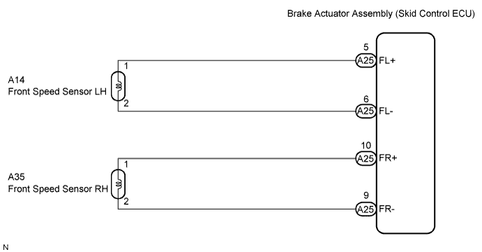
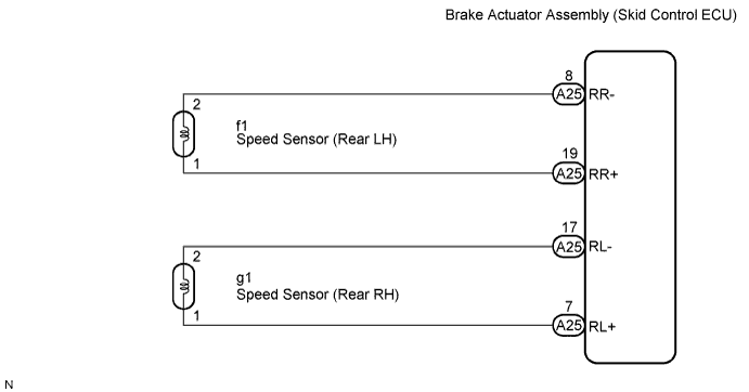
WIRING DIAGRAM
INSPECTION PROCEDURE
- HINT:
- Check the condition of each related circuit connector before troubleshooting (Click here).
| 1.CHECK TIRES |
Check the size and condition of all 4 tires (Click here).
- HINT:
- This DTC is output when tire deformation or a difference in tire size is detected.
- OK:
- The diameters of all 4 tires and air pressure are the same.
|
| ||||
| OK | |
| 2.INSPECT SPEED SENSOR AND SENSOR ROTOR SERRATIONS |
Disconnect the skid control ECU connector.
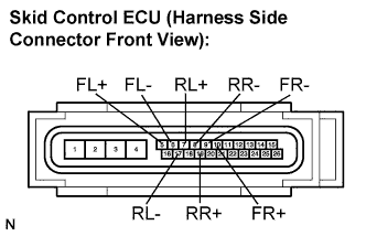 |
Connect the oscilloscope to each speed sensor terminal of the skid control ECU connector.
- Terminals:
Connector Circuit A25-5 (FL+) - A25-6 (FL-) Front left speed sensor A25-10 (FR+) - A25-9 (FR-) Front right speed sensor A25-7 (RL+) - A25-17 (RL-) Rear left speed sensor A25-19 (RR+) - A25-8 (RR-) Rear right speed sensor
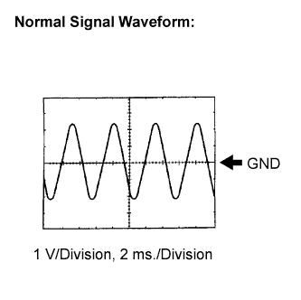
Check that a waveform is output when the tires are rotated (by the sensor circuit).
- OK:
- A waveform as shown in the figure should be output.
- HINT:
- Each sensor circuit outputs the same waveform without noise.
- As vehicle speed (wheel rotation speed) increases, the width of the waveform narrows and the output voltage becomes greater.
- When noise is identified in the waveform on the oscilloscope, the erratic signals are generated due to rotor scratches, looseness or foreign matter attached to the speed sensor.
 |
Make sure that the waveform does not change while jiggling a connector or a wire harness.
- OK:
- The waveform does not change.
- HINT:
- If the waveform changes while jiggling a connector or a wire harness, there may be a malfunction in the connector or the wire harness.
Connect the connector.
|
| ||||
| OK | |
| 3.RECONFIRM DTC |
Clear the DTC (Click here).
Start the engine.
Drive the vehicle at a speed of 32 km/h (20 mph) or more for 60 seconds or more.
Check if the same DTC is recorded (Click here).
- HINT:
- Reinstall the sensors, connectors, etc. and restore the vehicle to its prior condition before rechecking for DTCs.
- Result:
Condition Proceed to DTC is not output A DTC is output B
|
| ||||
| A | ||
| ||
| 4.CHECK SPEED SENSOR ROTOR |
Check the speed sensor rotor.
Front Speed Sensor Rotor: (Click here)
Rear Speed Sensor Rotor: (Click here)- OK:
- No scratches or foreign matter on the rotors.
- NOTICE:
- Check the speed sensor signal after the cleaning/replacement (Click here).
|
| ||||
| OK | |
| 5.CHECK SPEED SENSOR TIP |
Remove each speed sensor.
Check the speed sensor tip.
- OK:
- No scratches or foreign matter on the sensor tip.
- NOTICE:
- Check the speed sensor signal after the cleaning/replacement (Click here).
Install the speed sensor.
|
| ||||
| OK | |
| 6.INSPECT EACH SPEED SENSOR |
Disconnect each speed sensor connector.
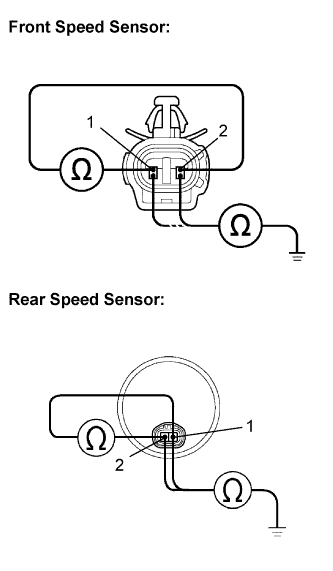 |
Measure the resistance according to the value(s) in the table below.
- Standard resistance:
- FRONT:
Tester Connection Condition Specified Condition A14-1 (FL+) - A14-2 (FL-) Always 1.4 to 1.8 kΩ at 20°C (68°F) A14-1 (FL+) - Body ground Always 10 kΩ or higher A14-2 (FL-) - Body ground Always 10 kΩ or higher A35-1 (FR+) - A35-2 (FR-) Always 1.4 to 1.8 kΩ at 20°C (68°F) A35-1 (FR+) - Body ground Always 10 kΩ or higher A35-2 (FR-) - Body ground Always 10 kΩ or higher - REAR:
Tester Connection Condition Specified Condition g1-1 (RL+) - g1-2 (RL-) Always Below 2.2 kΩ g1-1 (RL+) - Body ground Always 10 kΩ or higher g1-2 (RL-) - Body ground Always 10 kΩ or higher f1-1 (RR+) - f1-2 (RR-) Always Below 2.2 kΩ f1-1 (RR+) - Body ground Always 10 kΩ or higher f1-2 (RR-) - Body ground Always 10 kΩ or higher
Connect the connector.
- NOTICE:
- Check the speed sensor signal after replacement (Click here).
|
| ||||
| OK | |
| 7.CHECK HARNESS AND CONNECTOR (SKID CONTROL ECU TO EACH SPEED SENSOR) |
Disconnect the skid control ECU connector.
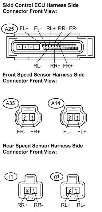 |
Measure the resistance according to the value(s) in the table below.
- Standard resistance:
- FRONT:
Tester Connection Condition Specified Condition A25-5 (FL+) - A14-1 (FL+) Always Below 1 Ω A25-6 (FL-) - A14-2 (FL-) Always Below 1 Ω A25-10 (FR+) - A35-1 (FR+) Always Below 1 Ω A25-9 (FR-) - A35-2 (FR-) Always Below 1 Ω A25-5 (FL+) - Body ground Always 10 kΩ or higher A25-6 (FL-) - Body ground Always 10 kΩ or higher A25-10 (FR+) - Body ground Always 10 kΩ or higher A25-9 (FR-) - Body ground Always 10 kΩ or higher - REAR:
Tester Connection Condition Specified Condition A25-7 (RL+) - g1-1 (RL+) Always Below 1 Ω A25-17 (RL-) - g1-2 (RL-) Always Below 1 Ω A25-19 (RR+) - f1-1 (RR+) Always Below 1 Ω A25-8 (RR-) - f1-2 (RR-) Always Below 1 Ω A25-7 (RL+) - Body ground Always 10 kΩ or higher A25-17 (RL-) - Body ground Always 10 kΩ or higher A25-19 (RR+) - Body ground Always 10 kΩ or higher A25-8 (RR-) - Body ground Always 10 kΩ or higher
Connect the connector.
|
| ||||
| OK | |
| 8.RECONFIRM DTC |
Clear the DTC (Click here).
Start the engine.
Drive the vehicle at the speed of 32 km/h (20 mph) or more for at least 60 seconds.
Check if the same DTC is recorded (Click here).
- HINT:
- Reinstall the sensors, connectors, etc. and restore the vehicle to its prior condition before rechecking for DTCs.
- Result:
Condition Proceed to DTC (C1237/37) is not output A DTC (C1237/37) is output B
|
| ||||
| A | ||
| ||